DTC    P0505    Idle Control System Malfunction

for Preparation Click here


DESCRIPTION

The idle speed is controlled by the electronic throttle control system. The electronic throttle control system is comprised of: 1) the one valve type throttle body assembly; 2) a throttle actuator, which operates the throttle valve; 3) a throttle position sensor, which detects the opening angle of the throttle valve; 4) an accelerator pedal position sensor, which detects the accelerator pedal position; and 5) the ECM, which controls the electronic throttle control system. Based on the target idle speed, the ECM controls the throttle actuator to provide the proper throttle valve opening angle.

DTC No.
DTC Detection Condition
Trouble Area
P0505
Idling speed continues to vary greatly from target idling speed (2 trip detection logic).
  1. Electronic throttle control system
  2. Intake system
  3. PCV hose connections
  4. EGR valve assembly
  5. ECM

MONITOR DESCRIPTION

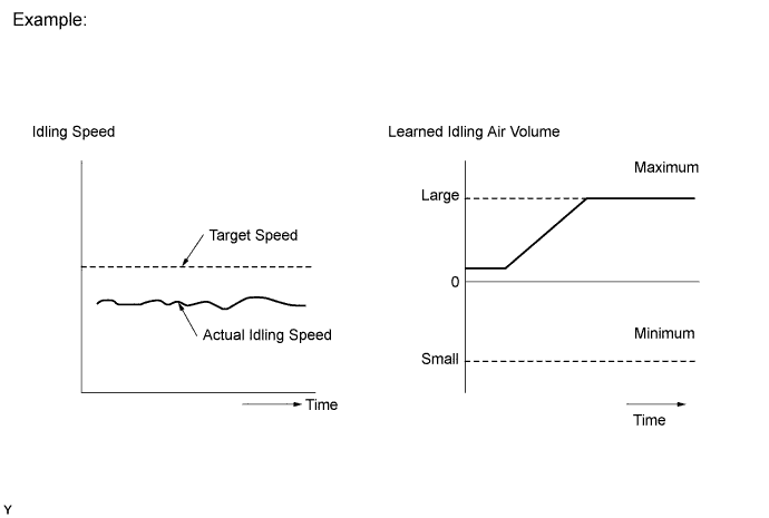
The ECM monitors the idling speed and idling air flow volume to conduct Idle Speed Control (ISC). The ECM determines that the ISC system is malfunctioning if the following condition is met:
  1. After driving at a vehicle speed of 10 km/h (6.25 mph) or more, the difference between the target and actual engine idling speed exceeds the threshold 5 times or more during a driving cycle, and then the system determines that the IAC flow rate learned value is stuck at the upper or lower limit, or that the IAC flow rate learned value has been changed by an amount that exceeds the threshold.

A121611E13


MONITOR STRATEGY


Required Sensors/Components (Main)
Electronic throttle control system
Required Sensors/Components (Related)
Crankshaft position sensor
Engine coolant temperature sensor
Vehicle speed sensor
Frequency of Operation
Once per driving cycle
MIL Operation
2 driving cycles

TYPICAL MALFUNCTION THRESHOLDS


Both of following conditions A and B met
-
A. Frequency that both of following conditions (a) and (b) met
5 times or more
(a) Engine speed - Target engine speed
Less than -100 rpm, or more than 150 rpm (A/C off and NSW off)
Less than -100 rpm, or more than 200 rpm (A/C on or NSW on)
(b) Vehicle condition
Stopped after being driven at 10 km/h (6.25 mph) or more
B. Either condition is met
(c) or (d)
(c) IAC flow rate learned value
Lower limit or upper limit
(d) Amount of change of IAC flow rate learned value exceeds threshold

CONFIRMATION DRIVING PATTERN


A249361E04

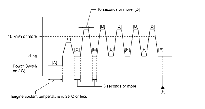
  1. Connect the intelligent tester to the DLC3.
  2. Turn the power switch on (IG) and turn the tester on.
  3. Enter the following menus: Powertrain / Engine and ECT / Data List / Coolant Temp.
  4. Make sure that the coolant temperature is 25°C (77°F) or less [A].
  5. Clear the DTCs (even if no DTCs are stored, perform the clear DTC operation).
  6. Turn the power switch off and wait for 30 seconds.
  7. Turn the power switch on (IG) and turn the tester on.
  8. Put the engine in inspection mode (maintenance mode) (Click here).
  9. Start the engine and drive the vehicle until the coolant temperature reaches 70°C (158°F) [B].

    CAUTION:
    When performing the confirmation driving pattern, obey all speed limits and traffic laws.

    HINT:
    If the coolant temperature is 40°C (104°F) or higher, the engine may stop when idling.

  10. Stop the vehicle (0 km/h [0 mph]) for 5 seconds or more [C].
  11. Accelerate the vehicle to 10 km/h (6.25 mph) or more for 10 seconds or more [D].

    CAUTION:
    When performing the confirmation driving pattern, obey all speed limits and traffic laws.

    HINT:
    1. When accelerating the vehicle, depress the accelerator pedal more than normal to start the engine.
    1. The engine may stop during acceleration. However, this will not affect the confirmation driving.

  12. Stop the vehicle (0 km/h [0 mph]) for 5 seconds or more [E].
  13. Repeat steps [D] and [E] for 5 times or more.
  14. Enter the following menus: Powertrain / Engine and ECT / DTC [F].
  15. Read the pending DTCs.

    HINT:
    1. If a pending DTC is output, the system is malfunctioning.
    2. If a pending DTC is not output, perform the following procedure.

  16. Enter the following menus: Powertrain / Engine and ECT / Utility / All Readiness.
  17. Input the DTC: P0505.
  18. Check the DTC judgment result.

    Tester Display
    Description
    NORMAL
    1. DTC judgment completed
    2. System normal
    ABNORMAL
    1. DTC judgment completed
    2. System abnormal
    INCOMPLETE
    1. DTC judgment not completed
    2. Perform driving pattern after confirming DTC enabling conditions
    UNKNOWN
    1. Unable to perform DTC judgment
    2. Number of DTCs which do not fulfill DTC preconditions has reached ECU's memory limit

    HINT:
    1. If the judgment result shows NORMAL, the system is normal.
    2. If the judgment result shows ABNORMAL, the system has a malfunction.
    3. If the judgment result shows INCOMPLETE or UNKNOWN, repeat steps [D] and [E] for 5 times or more.


INSPECTION PROCEDURE

HINT:
  1. The following conditions may also cause DTC P0505 to be set:
    1. The floor carpet overlapping slightly onto the accelerator pedal, causing the accelerator pedal to be slightly depressed and therefore the throttle valve position to be slightly open.
    2. The accelerator pedal being not fully released.
  2. Read freeze frame data using the intelligent tester. The ECM records vehicle and driving condition information as freeze frame data the moment a DTC is stored. When troubleshooting, freeze frame data can be helpful in determining whether the vehicle was running or stopped, whether the engine was warmed up or not, whether the air fuel ratio was lean or rich, as well as other data recorded at the time of a malfunction.
  3. Refer to "Data List / Active Test" [Engine Speed and ISC Learning Value] (Click here).

1.CHECK ANY OTHER DTCS OUTPUT (IN ADDITION TO DTC P0505)
  1. Connect the intelligent tester to the DLC3.

  1. Turn the power switch on (IG).

  1. Turn the tester on.

  1. Enter the following menus: Powertrain / Engine and ECT / DTC.

  1. Read the DTCs.
    Result 
    Result
    Proceed to
    DTC P0505 is output
    A
    DTC P0505 and other DTCs are output
    B

    HINT:
    If any DTCs other than P0505 are output, troubleshoot those DTCs first.


B
GO TO DTC CHART (Click here)
A


2.CHECK PCV HOSE CONNECTIONS
  1. Check the PCV hose connections.

    OK:
    PCV hose is connected correctly and is not damaged.


NG
REPAIR OR REPLACE PCV HOSE
OK


3.CHECK INTAKE SYSTEM
  1. Check the intake system for vacuum leaks (Click here).

    OK:
    No leaks from the intake system.


NG
REPAIR OR REPLACE INTAKE SYSTEM
OK


4.PERFORM ACTIVE TEST USING INTELLIGENT TESTER (CONTROL THE EGR STEP POSITION)
  1. Connect the intelligent tester to the DLC3.

  1. Turn the power switch on (IG).

  1. Turn the tester on.

  1. Put the engine in inspection mode (maintenance mode) (Click here).

  1. Start the engine and warm it up until the engine coolant temperature reaches 75°C (167°F) or higher.

    HINT:
    The A/C switch and all accessory switches should be off.

  1. Enter the following menus: Powertrain / Engine and ECT / Active Test / Control the EGR Step Position / Data List / All Data / Throttle Idle Position and MAP.

  1. Confirm that the Throttle Idle Position is ON and check the engine idling condition and MAP values in the Data List while performing the Active Test.

    HINT:
    1. Do not leave the EGR valve open for 10 seconds or more during the Active Test.
    2. Be sure to return the EGR valve to step 0 when the Active Test is completed.
    3. Do not open the EGR valve 30 steps or more during the Active Test.

    OK:
    MAP and idling condition change in response to EGR step position when Throttle Idle Position is ON in Data List.


    Standard:

    -
    EGR Step Position (Active Test)
    0 Steps
    0 to 30 Steps
    Idling condition
    Steady idling
    Idling changes from steady to rough idling or stalls
    MAP
    (Data List)
    MAP value is 20 to 40 kPa (150 to 300 mmHg)
    (EGR valve is fully closed)
    MAP value is at least +10 kPa (75 mmHg) higher than when EGR valve is fully closed

    HINT:
    During Active Test, if the idling condition does not change in response to EGR step position, then there is probably a malfunction in the EGR valve.

    Result 
    Result
    Proceed to
    Outside of standard range
    A
    Within standard range
    B


B
Go to step 6
A


5.INSPECT EGR VALVE ASSEMBLY
  1. Remove the EGR valve assembly (Click here).

  1. Check if the EGR valve is stuck open.

    OK:
    EGR valve is tightly closed.


NG
REPLACE EGR VALVE ASSEMBLY (Click here)
OK


6.INSPECT THROTTLE BODY ASSEMBLY
  1. Check for contamination between the throttle valve and the housing and then check that the throttle valve moves smoothly.

    OK:
    Throttle valve is not contaminated with foreign objects and moves smoothly.


NG
REPLACE THROTTLE BODY ASSEMBLY (Click here)
OK


7.CONFIRM WHETHER MALFUNCTION HAS BEEN SUCCESSFULLY REPAIRED
  1. Connect the intelligent tester to the DLC3.

  1. Turn the power switch on (IG).

  1. Turn the tester on.

  1. Clear the DTCs (Click here).

  1. Drive the vehicle in accordance with the driving pattern described in the Confirmation Driving Pattern.

  1. Enter the following menus: Powertrain / Engine and ECT / DTC.

  1. Read the pending DTCs.
    Result 
    Result
    Proceed to
    DTC P0505 is output
    A
    DTC is not output
    B


B
END
A

REPLACE ECM (Click here)