AIR CONDITIONING SYSTEM > Blower Motor Circuit |
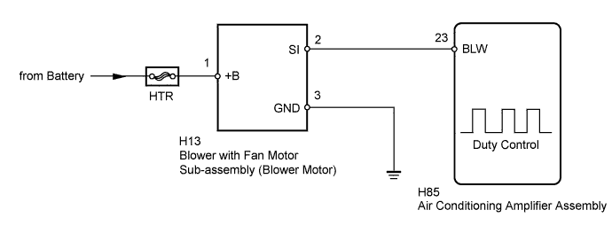
| 1.PERFORM ACTIVE TEST USING INTELLIGENT TESTER |
Connect the intelligent tester to the DLC3.
Turn the power switch on (IG).
Turn the intelligent tester on.
Enter the following menus: Body / Air Conditioner / Active Test.
Check the operation by referring to the table below.
| Tester Display | Test Part | Control Range | Diagnostic Note |
| Blower Motor | Blower with fan motor sub-assembly (blower motor) | Min.: 0, Max.: 31 | - |
| Result | Proceed to |
| OK | A |
| NG (Blower motor does not operate) | B |
| NG (Blower motor operates but does not change speed) | C |
|
| ||||
|
| ||||
| A | ||
 | ||
| ||
| 2.CHECK HARNESS AND CONNECTOR (BLOWER WITH FAN MOTOR (BLOWER MOTOR) - BODY GROUND) |
Disconnect the H13 blower with fan motor sub-assembly (blower motor) connector.
Measure the resistance according to the value(s) in the table below.
| Tester Connection | Condition | Specified Condition |
| H13-3 (GND) - Body ground | Always | Below 1 Ω |
|
| ||||
| OK | |
 |
| 3.CHECK HARNESS AND CONNECTOR (BLOWER WITH FAN MOTOR (BLOWER MOTOR) - POWER SOURCE) |
Measure the voltage according to the value(s) in the table below.
| Tester Connection | Condition | Specified Condition |
| H13-1 (+B) - Body ground | Power switch off | 11 to 14 V |
|
| ||||
| OK | |
|
| 4.CHECK HARNESS AND CONNECTOR (BLOWER MOTOR - AIR CONDITIONING AMPLIFIER) |
Disconnect the H85 air conditioning amplifier assembly connector.
Measure the resistance according to the value(s) in the table below.
| Tester Connection | Condition | Specified Condition |
| H85-23 (BLW) - H13-2 (SI) | Always | Below 1 Ω |
| H85-23 (BLW) - Body ground | Always | 10 kΩ or higher |
|
| ||||
| OK | |
|
| 5.INSPECT BLOWER WITH FAN MOTOR SUB-ASSEMBLY (BLOWER MOTOR) |
Reconnect the H13 blower with fan motor sub-assembly (blower motor) connector.
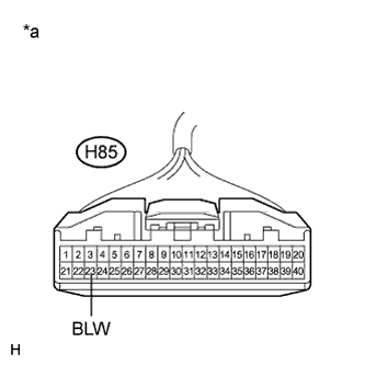 |
Measure the voltage according to the value(s) in the table below.
| Tester Connection | Condition | Specified Condition |
| H85-23 (BLW) - Body ground | Power switch off | 4.5 to 5.5 V |
| *a | Front view of wire harness connector (to Air Conditioning Amplifier Assembly) |
|
| ||||
| OK | |
|
| 6.INSPECT AIR CONDITIONING AMPLIFIER ASSEMBLY |
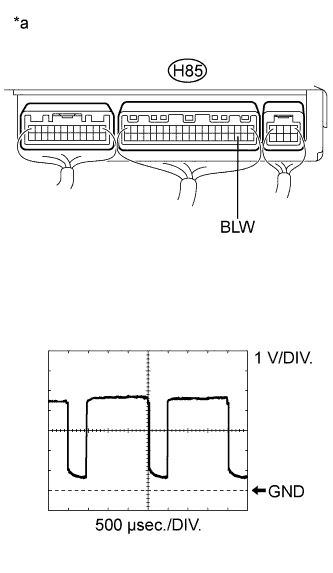 |
Remove the air conditioning amplifier assembly.
Reconnect the H85 air conditioning amplifier assembly connector.
Turn the power switch on (IG).
Set the blower speed to low.
Measure the waveform between terminal H85-23 (BLW) of the air conditioning amplifier assembly and body ground.
| Item | Content |
| Tool setting | 1 V/DIV., 500 μs/DIV. |
| Vehicle condition | Power switch on (IG) Blower set to low |
| *a | Component with harness connected (Air Conditioning Amplifier Assembly) |
|
| ||||
| OK | ||
| ||
| ||


