DTC B278A Short to GND in Immobiliser System Power Source Circuit |
| DTC Code | DTC Detection Condition | Trouble Area | DTC Output Confirmation Operation |
| B278A | A short to GND in the power supply of the transponder key amplifier of the power switch (VC5 - VC5) (1 trip detection logic*). |
| With park (P) selected, the key is held against the power switch and a hybrid control system start operation is performed by pressing and holding the power switch when the key battery is depleted. |
| Vehicle Condition when Malfunction Detected | Fail-safe Operation when Malfunction Detected |
| Hybrid control system cannot be started when key battery is depleted by holding key against power switch and pressing and holding power switch with park (P) selected | - |
| DTC Code | Data List and Active Test |
| B278A | - |
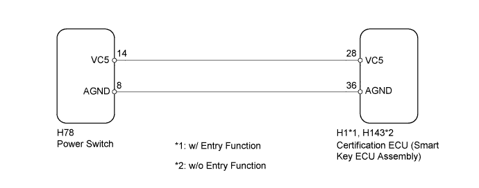
| 1.CHECK HARNESS AND CONNECTOR (CERTIFICATION ECU - POWER SWITCH) |
Disconnect the H1*1 or H143*2 ECU connector.
Disconnect the H78 switch connector.
Measure the resistance according to the value(s) in the table below.
| Tester Connection | Condition | Specified Condition |
| H1-28 (VC5) - H78-14 (VC5)*1 H143-28 (VC5) - H78-14 (VC5)*2 | Always | Below 1 Ω |
| H1-36 (AGND) - H78-8 (AGND)*1 H143-36 (AGND) - H78-8 (AGND)*2 | ||
| H1-28 (VC5) or H78-14 (VC5) - Body ground*1 H143-28 (VC5) or H78-14 (VC5) - Body ground*2 | Always | 10 kΩ or higher |
| H1-36 (AGND) or H78-8 (AGND) - Body ground*1 H143-36 (AGND) or H78-8 (AGND) - Body ground*2 |
|
| ||||
| OK | |
 |
| 2.CHECK CERTIFICATION ECU (SMART KEY ECU ASSEMBLY) |
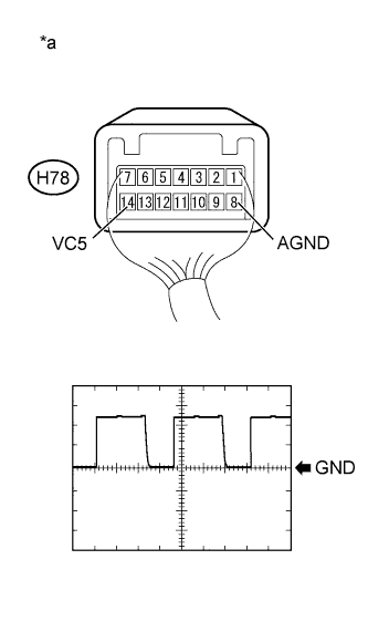 |
Using an oscilloscope, check the waveform.
| Item | Content |
| Tester Connection | H78-14 (VC5) - H78-8 (AGND) |
| Tool Setting | 2 V/DIV., 200 ms./DIV. |
| Condition | After power switch turned off, within 30 seconds of any door opened and closed, or brake pedal depressed |
| *a | Component with harness connected (Power Switch) |
|
| ||||
| OK | ||
 | ||
| ||

