SPIRAL CABLE > INSPECTION |
| 1. INSPECT SPIRAL CABLE WITH SENSOR SUB-ASSEMBLY |
Visually check for defects with the spiral cable with sensor sub-assembly removed from the vehicle.
The defects are as follows:
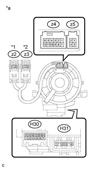 |
Check the spiral cable with sensor sub-assembly.
| *1 | Color: Orange |
| *2 | Color: Black |
| *a | Component without harness connected (Spiral Cable with Sensor Sub-assembly) |
Set the spiral cable with sensor sub-assembly to the center position.
Measure the resistance between each terminal of the spiral cable with sensor sub-assembly according to the table below.
| Tester Connection | Condition | Specified Condition |
| H30-1 (CCS) - z5-3 | Always | Below 1 Ω |
| H30-2 (ECC) - z5-4 | Always | Below 1 Ω |
| H30-2 (ECC) - z4-7 | Always | Below 1 Ω |
| H30-3 (EAU) - z4-8 | Always | Below 1 Ω |
| H30-5 (AU2) - z4-10 | Always | Below 1 Ω |
| H30-6 (AU1) - z4-11 | Always | Below 1 Ω |
| H30-8 (R/N) - z5-1 | Always | Below 1 Ω |
| H30-9 (HO) - z4-1 | Always | Below 1 Ω |
| H30-10 (+DP) - z4-2 | Always | Below 1 Ω |
| H30-11 (-DP) - z4-3 | Always | Below 1 Ω |
| H30-12 (DIST) - z4-4 | Always | Below 1 Ω |
| H30-13 (IL+2) - z4-5 | Always | Below 1 Ω |
| H31-1 (D+) - z2-2 (D+) | Always | Below 1 Ω |
| H31-2 (D-) - z2-1 (D-) | Always | Below 1 Ω |
| H31-3 (D2-) - z3-1 (D2-) | Always | Below 1 Ω |
| H31-4 (D2+) - z3-2 (D2+) | Always | Below 1 Ω |
After setting the spiral cable with sensor sub-assembly to the center position, rotate the spiral cable with sensor sub-assembly 2.5 times clockwise, and measure the resistance as shown in the table below. Then rotate the spiral cable with sensor sub-assembly 5 times counterclockwise, and measure the resistance as shown in the table below.
| Tester Connection | Condition | Specified Condition |
| H30-1 (CCS) - z5-3 | Always | Below 1 Ω |
| H30-2 (ECC) - z5-4 | Always | Below 1 Ω |
| H30-2 (ECC) - z4-7 | Always | Below 1 Ω |
| H30-3 (EAU) - z4-8 | Always | Below 1 Ω |
| H30-5 (AU2) - z4-10 | Always | Below 1 Ω |
| H30-6 (AU1) - z4-11 | Always | Below 1 Ω |
| H30-8 (R/N) - z5-1 | Always | Below 1 Ω |
| H30-9 (HO) - z4-1 | Always | Below 1 Ω |
| H30-10 (+DP) - z4-2 | Always | Below 1 Ω |
| H30-11 (-DP) - z4-3 | Always | Below 1 Ω |
| H30-12 (DIST) - z4-4 | Always | Below 1 Ω |
| H30-13 (IL+2) - z4-5 | Always | Below 1 Ω |
| H31-1 (D+) - z2-2 (D+) | Always | Below 1 Ω |
| H31-2 (D-) - z2-1 (D-) | Always | Below 1 Ω |
| H31-3 (D2-) - z3-1 (D2-) | Always | Below 1 Ω |
| H31-4 (D2+) - z3-2 (D2+) | Always | Below 1 Ω |
After setting the spiral cable with sensor sub-assembly to the center position, rotate the spiral cable with sensor sub-assembly 2.5 times clockwise. Then while rotating the spiral cable with sensor sub-assembly 5 times counterclockwise, measure the resistance as shown in the table below.
| Tester Connection | Condition | Specified Condition |
| H30-1 (CCS) - z5-3 | Always | Below 1 Ω |
| H30-2 (ECC) - z5-4 | Always | Below 1 Ω |
| H30-2 (ECC) - z4-7 | Always | Below 1 Ω |
| H30-3 (EAU) - z4-8 | Always | Below 1 Ω |
| H30-5 (AU2) - z4-10 | Always | Below 1 Ω |
| H30-6 (AU1) - z4-11 | Always | Below 1 Ω |
| H30-8 (R/N) - z5-1 | Always | Below 1 Ω |
| H30-9 (HO) - z4-1 | Always | Below 1 Ω |
| H30-10 (+DP) - z4-2 | Always | Below 1 Ω |
| H30-11 (-DP) - z4-3 | Always | Below 1 Ω |
| H30-12 (DIST) - z4-4 | Always | Below 1 Ω |
| H30-13 (IL+2) - z4-5 | Always | Below 1 Ω |
| H31-1 (D+) - z2-2 (D+) | Always | Below 1 Ω |
| H31-2 (D-) - z2-1 (D-) | Always | Below 1 Ω |
| H31-3 (D2-) - z3-1 (D2-) | Always | Below 1 Ω |
| H31-4 (D2+) - z3-2 (D2+) | Always | Below 1 Ω |
