HOW TO TROUBLESHOOT ECU CONTROLLED SYSTEMS > GENERAL INFORMATION |
| TROUBLESHOOTING PROCEDURES |
| Procedure Type | Details | Troubleshooting Method |
| DTC Based Diagnosis | The diagnosis procedure is based on the DTC that is stored. | The malfunctioning part is identified based on the DTC detection conditions using a process of elimination. The possible trouble areas are eliminated one-by-one by use of the intelligent tester and inspection of related parts. |
| Symptom Based Diagnosis (No DTCs stored) | The diagnosis procedure is based on problem symptoms. | The malfunctioning part is identified based on the problem symptoms using a process of elimination. The possible trouble areas are eliminated one-by-one by use of the intelligent tester and inspection of related parts. |
| DESCRIPTION |
The data of each system and Diagnostic Trouble Codes (DTCs) can be read from the Data Link Connector 3 (DLC3) of the vehicle. When the system seems to be malfunctioning, use the intelligent tester to check for malfunctions and perform repairs.
| CHECK DLC3 |
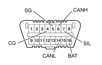 |
The vehicle ECUs use ISO 15765-4 communication protocol. The terminal arrangement of the DLC3 complies with ISO 15031-3 and matches the ISO 15765-4 format.
| Symbol | Terminal No. | Name | Reference Terminal | Result | Condition |
| SIL | 7 | Bus "+" line | 5 - Signal ground | Pulse generation | During transmission |
| CG | 4 | Chassis ground | Body ground | 1 Ω or less | Always |
| SG | 5 | Signal ground | Body ground | 1 Ω or less | Always |
| BAT | 16 | Auxiliary battery positive | Body ground | 11 to 14 V | Always |
| CANH | 6 | CAN "High" line | 14 - CANL | 54 to 69 Ω | power switch off* |
| Auxiliary battery positive | 6 kΩ or higher | power switch off* | |||
| 4 - CG | 200 Ω or higher | power switch off* | |||
| CANL | 14 | CAN "Low" line | Auxiliary battery positive | 6 kΩ or higher | power switch off* |
| 4 - CG | 200 Ω or higher | power switch off* |
