SLIDING ROOF SYSTEM > Sliding Roof does not Move by Operating Sliding Roof Control Switch |
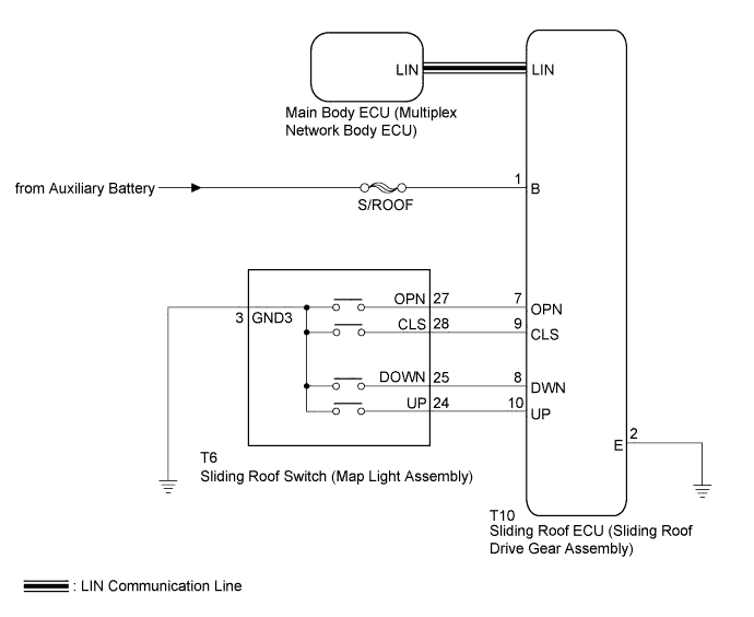
| 1.READ VALUE USING INTELLIGENT TESTER |
Connect the intelligent tester to the DLC3.
Turn the power switch on (IG).
Turn the intelligent tester on.
Enter the following menus: Body / Sliding Roof / Data List.
Read the Data List according to the display on the intelligent tester.
| Tester Display | Measurement Item/Range | Normal Condition | Diagnostic Note |
| Open Switch | SLIDE OPEN switch signal / ON or OFF | ON: SLIDE OPEN switch pressed OFF: SLIDE OPEN switch not pressed | - |
| Close Switch | SLIDE CLOSE switch signal / ON or OFF | ON: SLIDE CLOSE switch pressed OFF: SLIDE CLOSE switch not pressed | - |
| Up Switch | TILT UP switch signal / ON or OFF | ON: TILT UP switch pressed OFF: TILT UP switch not pressed | - |
| Down Switch | TILT DOWN switch signal / ON or OFF | ON: TILT DOWN switch pressed OFF: TILT DOWN switch not pressed | - |
|
| ||||
| OK | |
 |
| 2.CHECK HARNESS AND CONNECTOR (SLIDING ROOF ECU - AUXILIARY BATTERY, BODY GROUND) |
Disconnect the T10 sliding roof ECU (sliding roof drive gear assembly) connector.
Measure the voltage according to the value(s) in the table below.
| Tester Connection | Condition | Specified Condition |
| T10-1 (B) - Body ground | Power switch off | 11 to 14 V |
Measure the resistance according to the value(s) in the table below.
| Tester Connection | Condition | Specified Condition |
| T10-2 (E) - Body ground | Always | Below 1 Ω |
|
| ||||
| OK | ||
 | ||
| ||
| 3.INSPECT SLIDING ROOF SWITCH (MAP LIGHT ASSEMBLY) |
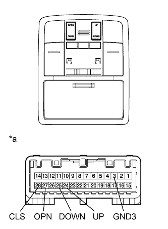 |
Remove the sliding roof switch (map light assembly) (Click here).
Measure the resistance according to the value(s) in the table below.
| Tester Connection | Switch Condition | Specified Condition |
| 25 (DOWN) - 3 (GND3) | TILT DOWN switch is pressed | Below 1 Ω |
| 25 (DOWN) - 3 (GND3) | TILT DOWN switch is not pressed | 10 kΩ or higher |
| 24 (UP) - 3 (GND3) | TILT UP switch is pressed | Below 1 Ω |
| 24 (UP) - 3 (GND3) | TILT UP switch is not pressed | 10 kΩ or higher |
| 28 (CLS) - 3 (GND3) | SLIDE CLOSE switch is pressed | Below 1 Ω |
| 28 (CLS) - 3 (GND3) | SLIDE CLOSE switch is not pressed | 10 kΩ or higher |
| 27 (OPN) - 3 (GND3) | SLIDE OPEN switch is pressed | Below 1 Ω |
| 27 (OPN) - 3 (GND3) | SLIDE OPEN switch is not pressed | 10 kΩ or higher |
| *a | Component without harness connected (Sliding Roof Switch (Map Light Assembly)) |
|
| ||||
| OK | |
|
| 4.CHECK HARNESS AND CONNECTOR (SLIDING ROOF ECU - SLIDING ROOF SWITCH) |
Disconnect the T6 sliding roof switch (map light assembly) connector.
Disconnect the T10 sliding roof ECU (sliding roof drive gear assembly) connector.
Measure the resistance according to the value(s) in the table below.
| Tester Connection | Condition | Specified Condition |
| T10-9 (CLS) - T6-28 (CLS) | Always | Below 1 Ω |
| T10-9 (CLS) - Body ground | Always | 10 kΩ or higher |
| T10-7 (OPN) - T6-27 (OPN) | Always | Below 1 Ω |
| T10-7 (OPN) - Body ground | Always | 10 kΩ or higher |
| T10-8 (DWN) - T6-25 (DOWN) | Always | Below 1 Ω |
| T10-8 (DWN) - Body ground | Always | 10 kΩ or higher |
| T10-10 (UP) - T6-24 (UP) | Always | Below 1 Ω |
| T10-10 (UP) - Body ground | Always | 10 kΩ or higher |
| T6-3 (GND3) - Body ground | Always | Below 1 Ω |
| T10-2 (E) - Body ground | Always | Below 1 Ω |
|
| ||||
| OK | ||
| ||
| ||


