DYNAMIC RADAR CRUISE CONTROL SYSTEM > TERMINALS OF ECU |
| CHECK DRIVING SUPPORT ECU |
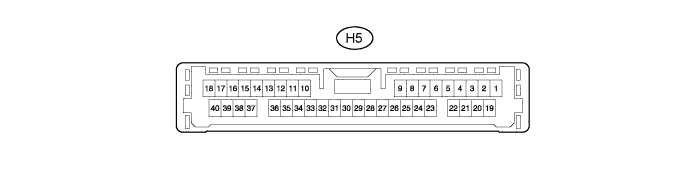
| Terminal No. (Symbol) | Wiring Color | Terminal Description | Condition | Specified Condition |
| H5-7 (MODE) - H5-25 (GND) | R - W-B | Steering pad switch signal (distance control signal) | Power switch on (IG) Distance control switch off | 11 to 14 V |
| H5-7 (MODE) - H5-25 (GND) | R - W-B | Steering pad switch signal (distance control signal) | Power switch on (IG) Distance control switch on | 6 to 7 V |
| H5-10 (CCHG) - H5-25 (GND) | V - W-B | Cruise control switch signal | Power switch on (IG), MODE switch off | 11 to 14 V |
| H5-10 (CCHG) - H5-25 (GND) | V - W-B | Cruise control switch signal | Power switch on (IG), MODE switch on | Below 1 V |
| H5-17 (CA2L) - H5-25 (GND) | B - W-B | CAN communication signal | Power switch on (IG) | Pulse generation (See waveform 1) |
| H5-16 (LRDD) - H5-25 (GND) | SB - W-B | Millimeter wave radar sensor | Power switch on (IG) | Pulse generation (See waveform 2) |
| H5-23 (CCS) - H5-25 (GND) | LG - W-B | Cruise control switch signal | Power switch on (IG) | 11 to 14 V |
| H5-23 (CCS) - H5-25 (GND) | LG - W-B | Cruise control switch signal | Power switch on (IG), CANCEL switch on | 6.6 to 10.1 V |
| H5-23 (CCS) - H5-25 (GND) | LG - W-B | Cruise control switch signal | Power switch on (IG), -/SET switch on | 4.5 to 7.1 V |
| H5-23 (CCS) - H5-25 (GND) | LG - W-B | Cruise control switch signal | Power switch on (IG), +/RES switch on | 2.3 to 4.0 V |
| H5-23 (CCS) - H5-25 (GND) | LG - W-B | Cruise control switch signal | Power switch on (IG), Cruise control switch on | Below 1 V |
| H5-25 (GND) - Body ground | W-B - Body ground | Earth (ground circuit of driving support ECU) | Always | Below 1 Ω |
| H5-27 (STP-) - H5-25 (GND) | Y - W-B | Stop light signal | Brake pedal released | Below 1 V |
| H5-27 (STP-) - H5-25 (GND) | Y - W-B | Stop light signal | Brake pedal depressed | 11 to 14 V |
| H5-28 (ST1-) - H5-25 (GND) | R - W-B | Stop light signal | Power switch on (IG), Brake pedal released | 11 to 14 V |
| H5-28 (ST1-) - H5-25 (GND) | R - W-B | Stop light signal | Power switch on (IG), Brake pedal depressed | Below 1 V |
| H5-30 (B) - H5-25 (GND) | BE - W-B | Power source | Power switch on (IG) | 11 to 14 V |
| H5-32 (WIP2) - H5-25 (GND) | P - W-B | Wiper switch signal | Power switch on (IG), Wiper switch off | Below 1 V |
| H5-32 (WIP2) - H5-25 (GND) | P - W-B | Wiper switch signal | Power switch on (IG), Wiper switch LO position | 6 to 7 V |
| H5-32 (WIP2) - H5-25 (GND) | P - W-B | Wiper switch signal | Power switch on (IG), Wiper switch HI position | 11 to 14 V |
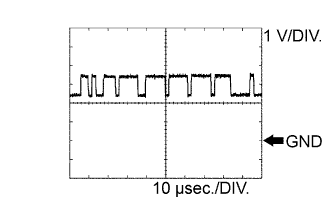
| H5-38 (LRRD) - H5-25 (GND) | R - W-B | Millimeter wave radar sensor output signal | Power switch on (IG) | Pulse generation (See waveform 3) |
| H5-39 (CA2H) - H5-25 (GND) | L - W-B | CAN communication signal | Power switch on (IG) | Pulse generation (See waveform 4) |
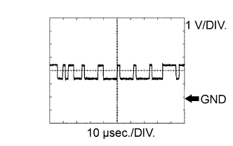 |
WAVEFORM 1
CAN communication signal
| Driving support ECU Terminal Name | Between H5-17 (CA2L) and H5-25 (GND) |
| Tester Range | 1 V/DIV., 10 μsec./DIV. |
| Condition | Power switch on (IG) |
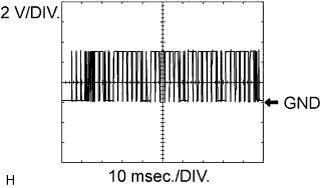 |
WAVEFORM 2
Millimeter wave radar sensor input signal
| Driving support ECU Terminal Name | Between H5-16 (LRDD) and H5-25 (GND) |
| Tester Range | 2 V/DIV., 10 μsec./DIV. |
| Condition | Power switch on (IG) |
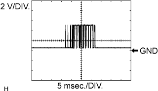 |
WAVEFORM 3
Millimeter wave radar sensor output signal
| Driving support ECU Terminal Name | Between H5-38 (LRRD) and H5-25 (GND) |
| Tester Range | 2 V/DIV., 5 μsec./DIV. |
| Condition | Power switch on (IG) |
 |
WAVEFORM 4
CAN communication signal
| Driving support ECU Terminal Name | Between H5-39 (CA2H) and H5-25 (GND) |
| Tester Range | 1 V/DIV., 10 μsec./DIV. |
| Condition | Power switch on (IG) |
| CHECK POWER MANAGEMENT CONTROL ECU |
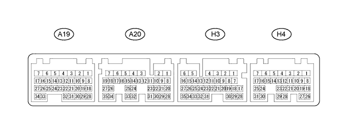
| Terminal No. (Symbol) | Wiring Color | Terminal Description | Condition | Specified Condition |
| H3-6 (E1) - Body ground | W-B - Body ground | Earth (ground) circuit of power management control ECU | Always | Below 1 Ω |
| H3-11 (TC) - H3-6 (E1) | L - W-B | Terminal TC of DLC3 | Power switch on (IG) | 11 to 14 V |
| H3-11 (TC) - H3-6 (E1) | L - W-B | Terminal TC of DLC3 | Terminals TC and CG of DLC3 connected | Below 1 V |
| H3-34 (CA2H) - H3-6 (E1) | R - W-B | CAN communication line | Power switch on (IG) | Pulse generation (see waveform 1) |
| H3-35 (CA2L) - H3-6 (E1) | B - W-B | CAN communication line | Power switch on (IG) | Pulse generation (see waveform 2) |
| H4-24 (CA1L) - H3-6 (E1) | V - W-B | CAN communication line | Power switch on (IG) | Pulse generation (see waveform 2) |
| H4-25 (CA1H) - H3-6 (E1) | P - W-B | CAN communication line | Power switch on (IG) | Pulse generation (see waveform 1) |
|
WAVEFORM 1
CAN communication signal
| Power management control ECU Terminal Name | Between H4-25 (CA1H) - H3-6 (E1) or H3-34 (CA2H) - H3-6 (E1) |
| Tester Range | 1 V/DIV., 10 μsec./DIV. |
| Condition | Power switch on (IG) |
|
WAVEFORM 2
CAN communication signal
| Power management control ECU Terminal Name | Between H4-24 (CA1L) - H3-6 (E1) or H3-35 (CA2L) - H3-6 (E1) |
| Tester Range | 1 V/DIV., 10 μsec./DIV. |
| Condition | Power switch on (IG) |
