DYNAMIC RADAR CRUISE CONTROL SYSTEM > Distance Control Switch Circuit |
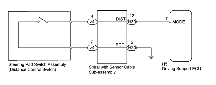
| 1.READ VALUE USING INTELLIGENT TESTER (DISTANCE CONTROL SWITCH) |
Connect the intelligent tester to the DLC3.
Turn the power switch on (IG).
Turn the intelligent tester on.
Enter the following menus: Powertrain / Radar Cruise / Data List.
Check the Data List to confirm function of the distance control switch.
| Tester Display | Measurement Item/Range | Normal Condition | Diagnostic Note |
| Distance Control Switch | Distance control switch signal / ON or OFF | ON: Distance control switch on OFF: Distance control switch off | - |
|
| ||||
| OK | ||
 | ||
| ||
| 2.INSPECT STEERING PAD SWITCH ASSEMBLY |
Remove the steering pad switch assembly (Click here).
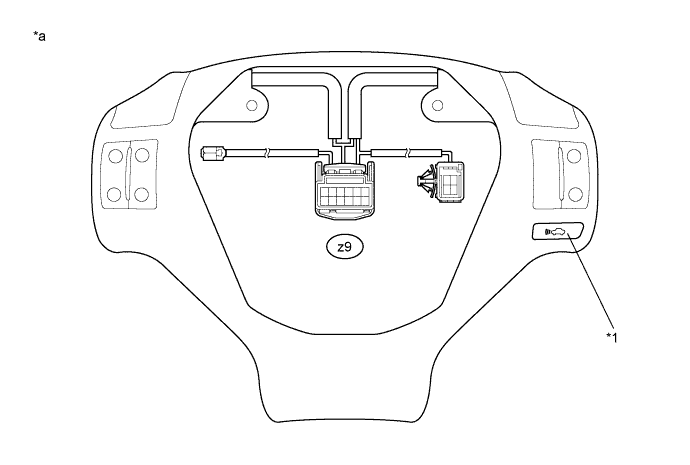
| *a | Component without harness connected (Steering Pad Switch Assembly) | *1 | Distance Control Switch |
Measure the resistance according to the value(s) in the table below.
| Tester Connection | Switch Condition | Specified Condition |
| z4-4 - z4-7 | Distance control switch ON | Below 2.5 Ω |
| z4-4 - z4-7 | Distance control switch OFF | 1 MΩ or higher |
Install the steering pad switch assembly (Click here).
|
| ||||
| OK | |
 |
| 3.INSPECT SPIRAL WITH SENSOR CABLE SUB-ASSEMBLY |
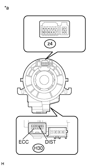 |
Remove the spiral with sensor cable sub-assembly (Click here).
Measure the resistance according to the value(s) in the table below.
| Tester Connection | Condition | Specified Condition |
| z4-4 - H30-12 (DIST) | The spiral with sensor cable sub-assembly is centered | Below 1 Ω |
| The spiral with sensor cable sub-assembly position is 2.5 rotations to the left | ||
| The spiral with sensor cable sub-assembly position is 2.5 rotations to the right | ||
| z4-7 - H30-2 (ECC) | The spiral with sensor cable sub-assembly is centered | Below 1 Ω |
| The spiral with sensor cable sub-assembly position is 2.5 rotations to the left | ||
| The spiral with sensor cable sub-assembly position is 2.5 rotations to the right |
| *a | Component without harness connected (Spiral with Sensor Cable Sub-assembly) |
Reinstall the spiral with sensor cable sub-assembly (Click here).
|
| ||||
| OK | |
|
| 4.CHECK HARNESS AND CONNECTOR (SPIRAL WITH SENSOR CABLE SUB-ASSEMBLY - DRIVING SUPPORT ECU) |
Disconnect the driving support ECU assembly connector.
Disconnect the spiral with sensor cable sub-assembly connector.
Measure the resistance according to the value(s) in the table below.
| Tester Connection | Condition | Specified Condition |
| H5-7 (MODE) - H30-12 (DIST) | Always | Below 1 Ω |
| H5-7 (MODE) or H30-12 (DIST) - Body ground | Always | Below 1 Ω |
Reconnect the driving support ECU assembly connector.
Reconnect the spiral with sensor cable sub-assembly connector.
|
| ||||
| OK | |
|
| 5.CHECK HARNESS AND CONNECTOR (SPIRAL WITH SENSOR CABLE SUB-ASSEMBLY - BODY GROUND) |
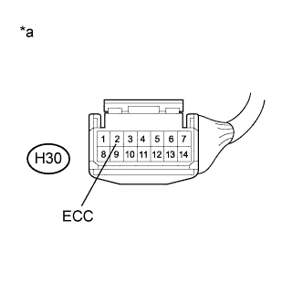 |
Disconnect the spiral with sensor cable sub-assembly connector.
Measure the resistance according to the value(s) in the table below.
| Tester Connection | Condition | Specified Condition |
| H30-2 (ECC) - Body ground | Always | Below 1 Ω |
| *a | Front view of wire harness connector (to Spiral with Sensor Cable Sub-assembly) |
Reconnect the spiral with sensor cable sub-assembly connector.
|
| ||||
| OK | ||
| ||
| ||


