DYNAMIC RADAR CRUISE CONTROL SYSTEM > Wiper Signal Circuit |
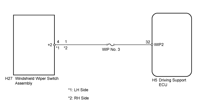
| 1.INSPECT DRIVING SUPPORT ECU |
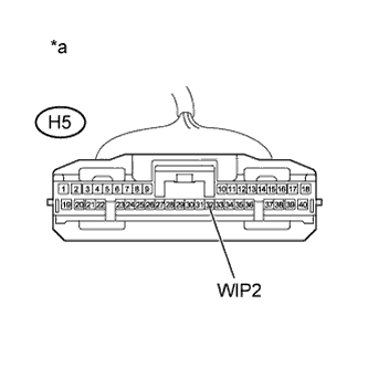 |
Disconnect the driving support ECU connector.
Turn the power switch on (IG).
Set the windshield wiper switch assembly to the HI position.
Measure the voltage according to the value(s) in the table below.
| Tester Connection | Condition | Specified Condition |
| H5-32 (WIP2) - Body ground | Power switch on (IG), windshield wiper switch assembly Hi position | 11 to 14 V |
| *a | Front view of wire harness connector (to Driving Support ECU) |
Reconnect the driving support ECU connector.
|
| ||||
| OK | ||
 | ||
| ||
| 2.CHECK HARNESS AND CONNECTOR (DRIVING SUPPORT CONTROL ECU - WINDSHIELD WIPER SWITCH) |
Disconnect the driving support ECU connector.
Disconnect the windshield wiper switch assembly connector.
Measure the resistance according to the value(s) in the table below.
| Tester Connection | Condition | Specified Condition |
| H5-32 (WIP2) - H27-4 (+2) | Always | Below 1 Ω |
| Tester Connection | Condition | Specified Condition |
| H5-32 (WIP2) - H27-1 (+2) | Always | Below 1 Ω |
| Tester Connection | Condition | Specified Condition |
| H5-32 (WIP2) or H27-4 (+2) - Body ground | Always | 10 kΩ or higher |
| Tester Connection | Condition | Specified Condition |
| H5-32 (WIP2) or H27-1 (+2) - Body ground | Always | 10 kΩ or higher |
Reconnect the driving support ECU connector.
Reconnect the windshield wiper switch assembly connector.
|
| ||||
| OK | ||
| ||
| ||


