METER / GAUGE SYSTEM > Tachometer Malfunction |
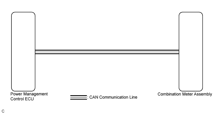
| 1.CHECK CAN COMMUNICATION SYSTEM |
Check if a CAN communication DTC is output (Click here).
| Result | Proceed to |
| CAN communication DTC is not output. | A |
| CAN communication DTC is output. | B |
|
| ||||
| A | |
 |
| 2.PERFORM ACTIVE TEST USING INTELLIGENT TESTER (TACHO METER OPERATION) |
Connect the intelligent tester to the DLC3.
Turn the power switch on (IG).
Turn the intelligent tester on.
Enter the following menus: Body / Combination Meter / Active Test.
Check the operation by referring to the table below.
| Tester Display | Test Part | Control Range | Diagnostic Note |
| Tacho Meter Operation | Tachometer | 0, 1000, 2000, 3000, 4000, 5000, 6000, 7000 (rpm) | - |
|
| ||||
| OK | |
|
| 3.READ VALUE USING INTELLIGENT TESTER (ENGINE RPM) |
Connect the intelligent tester to the DLC3.
Turn the power switch on (IG).
Turn the intelligent tester on.
Enter the following menus: Body / Combination Meter / Data List.
Check the values by referring to the table below.
| Tester Display | Measurement Item/Range | Normal Condition | Diagnostic Note |
| Engine Rpm | Engine speed/Min.: 0 rpm, Max.: 12750 rpm | 600 to 700 rpm (When idling) | If data received from the ECM exceeds the range that can be displayed on the meter, the meter continues to display the maximum value of the range. |
Record the engine speed displayed on the intelligent tester.
|
| ||||
| OK | |
|
| 4.READ VALUE USING INTELLIGENT TESTER (ENGINE REVOLUTION) |
Connect the intelligent tester to the DLC3.
Turn the power switch on (IG).
Turn the intelligent tester on.
Enter the following menus: Powertrain / Hybrid Control / Data List.
Set the vehicle in the maintenance mode using the intelligent tester (Click here).
Check the values by referring to the table below.
| Tester Display | Measurement Item/Range | Normal Condition | Diagnostic Note |
| Engine Revolution | Engine speed/ Min.: 0 rpm, Max.: 16383.75 rpm |
| - |
|
| ||||
| OK | |
|
| 5.REPLACE POWER MANAGEMENT CONTROL ECU |
Replace the power management control ECU with a new or a known good one (Click here).
|
| ||||
| OK | ||
 | ||
| ||

