PRE-CRASH SAFETY SYSTEM > TERMINALS OF ECU |
| CHECK SEAT BELT CONTROL ECU |
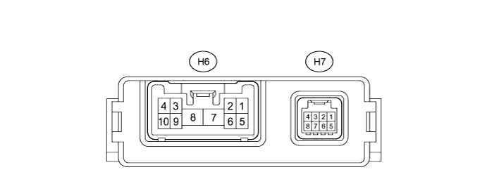
Disconnect the seat belt control ECU connectors.
Measure the resistance and voltage according to the value(s) in the table below.
| Terminal No. (Symbol) | Wiring Color | Terminal Description | Condition | Specified Condition |
| H6-7 (+B) - Body ground | B - Body ground | Auxiliary battery voltage | Power switch off | 11 to 14 V |
| H6-8 (PGND) - Body ground | W-B - Body ground | Body ground | Always | Below 1 Ω |
| H7-8 (IG1) - Body ground | L - Body ground | Seat belt control ECU power supply | Power switch on (IG) | 11 to 14 V |
| Power switch off | Below 1 V |
Reconnect the connectors.
Measure the voltage according to the value(s) in the table below.
| Terminal No. (Symbol) | Wiring Color | Terminal Description | Condition | Specified Condition |
| H6-2 (MOR+) - H6-1 (MOR-) | B - W | Seat belt motor RH power supply | Power switch on (IG) | 4.0 to 8.5 V |
| Power switch off | Below 1 V | |||
| H6-3 (MOL+) - H6-4 (MOL-) | B - W | Seat belt motor LH power supply | Power switch on (IG) | 4.0 to 8.5 V |
| Power switch off | Below 1 V |
| CHECK DRIVING SUPPORT ECU |
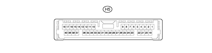
Disconnect the driving support ECU connector.
Measure the resistance according to the value(s) in the table below.
| Terminal No. (Symbol) | Wiring Color | Terminal Description | Condition | Specified Condition |
| H5-25 (GND) - Body ground | W-B - Body ground | Body ground | Always | Below 1 Ω |
| H5-5 (PBSW)* - Body ground | L - Body ground | Pre-crash brake cancel switch | Pre-crash brake cancel switch assembly on | Below 1 Ω |
| Pre-crash brake cancel switch assembly off | 10 kΩ or higher |
Reconnect the connector.
Measure the voltage according to the value(s) in the table below.
| Terminal No. (Symbols) | Wiring Color | Terminal Description | Condition | Specified Condition |
| H5-17 (CA2L) - H5-25 (GND) | B - W-B | CAN communication signal | Power switch on (IG) | Pulse generation (See waveform 1) |
| H5-7 (MODE) - Body ground | R - Body ground | MODE signal | Power switch on (IG) MODE switch off | 11 to 14 V |
| Power switch on (IG) MODE switch on | Below 1 V | |||
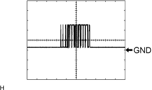
| H5-16 (LRDD) - Body ground | SB - Body ground | Driving support ECU communication signal | Power switch on (IG) | Pulse generation (See waveform 2) |
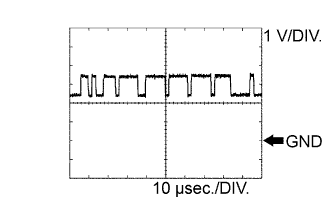
| H5-38 (LRRD) - Body ground | R - Body ground | Driving support ECU communication signal | Power switch on (IG) | Pulse generation (See waveform 3) |
| H5-23 (CCS) - H5-25 (GND) | LG - W-B | Cruise control main switch signal | Power switch on (IG) | 10 to 14 V |
| H5-23 (CCS) - H5-25 (GND) | LG - W-B | Cruise control main switch signal | Power switch on (IG), CANCEL switch on | 6.6 to 10.1 V |
| H5-23 (CCS) - H5-25 (GND) | LG - W-B | Cruise control main switch signal | Power switch on (IG), Main switch on | Below 1 V |
| H5-39 (CA2H) - H5-25 (GND) | L - W-B | CAN communication signal | Power switch on (IG) | Pulse generation (See waveform 4) |
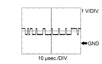 |
Waveform 1
CAN communication signal
| Item | Content |
| Driving Support ECU Terminal Name | Between CA2L and GND |
| Tester Range | 1 V/DIV., 10 μsec./DIV. |
| Condition | Power switch on (IG) |
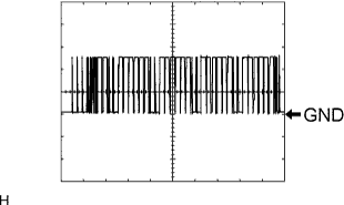 |
Waveform 2
| Item | Content |
| Driving Support ECU Terminal Name | Between LRDD and GND |
| Tester Range | 2 V/DIV., 10 μsec./DIV. |
| Condition | Power switch on (IG) |
 |
Waveform 3
| Item | Content |
| Driving Support ECU Terminal Name | Between LRRD and GND |
| Tester Range | 2 V/DIV., 10 μsec./DIV. |
| Condition | Power switch on (IG) |
 |
Waveform 4
CAN communication signal
| Item | Content |
| Driving Support ECU Terminal Name | Between CA2H and GND |
| Tester Range | 1 V/DIV., 10 μsec./DIV. |
| Condition | Power switch on (IG) |
