PRE-CRASH SAFETY SYSTEM > Power Source Circuit |
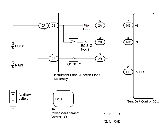
| 1.CHECK HARNESS AND CONNECTOR (GND CIRCUIT) |
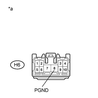 |
Disconnect the seat belt control ECU connector.
Measure the resistance according to the value(s) in the table below.
| Tester Display | Condition | Specified Condition |
| H6-8 (PGND) - Body ground | Always | Below 1 Ω |
| *a | Front view of wire harness connector (to Seat Belt Control ECU) |
Reconnect the seat belt control ECU connector.
|
| ||||
| OK | |
 |
| 2.CHECK HARNESS AND CONNECTOR (IG1 CIRCUIT) |
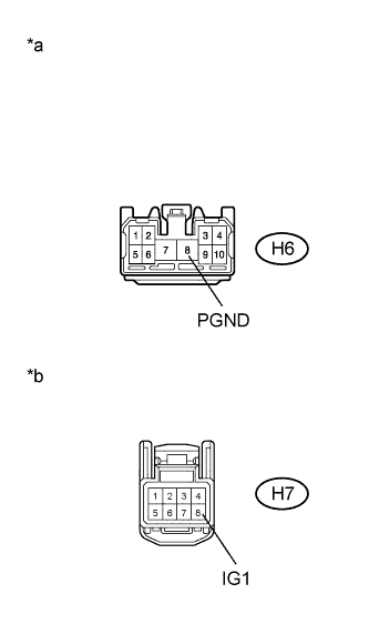 |
Disconnect the seat belt control ECU connector.
Turn the power switch on (IG).
Measure the voltage according to the value(s) in the table below.
| Tester Display | Condition | Specified Condition |
| H7-8 (IG1) - H6-8 (PGND) | Power switch on (IG) | 11 to 14 V |
| *a | Front view of wire harness connector (to Seat Belt Control ECU) |
| *b | Front view of wire harness connector (to Seat Belt Control ECU) |
Reconnect the seat belt control ECU connector.
|
| ||||
| OK | |
|
| 3.CHECK HARNESS AND CONNECTOR (+B CIRCUIT) |
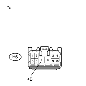 |
Disconnect the seat belt control ECU connector.
Measure the voltage according to the value(s) in the table below.
| Tester Display | Condition | Specified Condition |
| H6-7 (+B) - Body ground | Power switch off | 11 to 14 V |
| *a | Front view of wire harness connector (to Seat Belt Control ECU) |
Reconnect the seat belt control ECU connector.
|
| ||||
| OK | ||
 | ||
| ||
| 4.INSPECT INSTRUMENT PANEL JUNCTION BLOCK ASSEMBLY |
Remove the instrument panel junction block assembly (Click here).
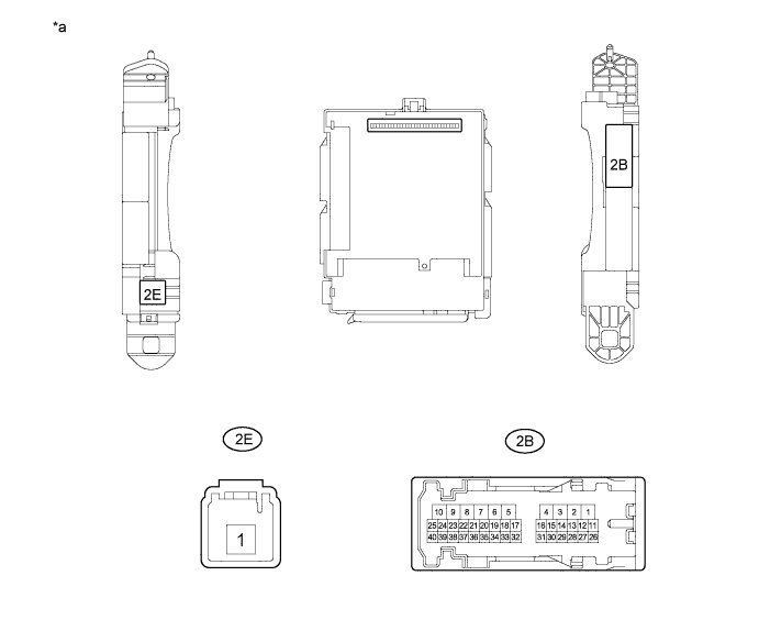
| *a | Component without harness connected (Instrument Panel Junction Block Assembly) | - | - |
Measure the resistance according to the value(s) in the table below.
| Tester Connection | Condition | Specified Condition |
| 2E*1-1 - 2B-2 | Always | 10 kΩ or higher |
| 2F*2-1 - 2B-2 | ||
| 2E*1-1 - 2B-2 | When auxiliary battery voltage applied to terminals 2B-25 and 2B-6 | Below 1 Ω |
| 2F*2-1 - 2B-2 |
Reinstall the instrument panel junction block assembly.
|
| ||||
| OK | |
|
| 5.CHECK HARNESS AND CONNECTOR (INSTRUMENT PANEL JUNCTION BLOCK - SEAT BELT CONTROL ECU) |
Disconnect the instrument panel junction block assembly connector.
Disconnect the seat belt control ECU connector.
Measure the resistance according to the value(s) in the table below.
| Tester Connection | Condition | Specified Condition |
| 2B-2 - H7-8 (IG1) | Always | Below 1 Ω |
| 2B-2 - Body ground | Always | 10 kΩ or higher |
| H7-8 (IG1) - Body ground | Always | 10 kΩ or higher |
Reconnect the seat belt control ECU connector.
Reconnect the instrument panel junction block assembly connector.
|
| ||||
| OK | |
|
| 6.CHECK HARNESS AND CONNECTOR (INSTRUMENT PANEL JUNCTION BLOCK ASSEMBLY - BODY GROUND) |
Disconnect the instrument panel junction block assembly connector.
Measure the resistance according to the value(s) in the table below.
| Tester Connection | Condition | Specified Condition |
| 2B-6 - Body ground | Always | Below 1 Ω |
Reconnect the instrument panel junction block assembly connector.
|
| ||||
| OK | |
|
| 7.CHECK HARNESS AND CONNECTOR (INSTRUMENT PANEL JUNCTION BLOCK - POWER MANAGEMENT ECU) |
Disconnect the instrument panel junction block assembly connector.
Disconnect the power management control ECU connector.
Measure the resistance according to the value(s) in the table below.
| Tester Connection | Condition | Specified Condition |
| 2B-25 - H4-2 (IG1D) | Always | Below 1 Ω |
| 2B-25 - Body ground | Always | 10 kΩ or higher |
| H4-2 (IG1D) - Body ground | Always | 10 kΩ or higher |
Reconnect the power management control ECU connector.
Reconnect the instrument panel junction block assembly connector.
|
| ||||
| OK | ||
| ||
| ||


