INVERTER WITH CONVERTER > INSTALLATION

for Preparation Click here


1. INSTALL HIGH VOLTAGE FUSE

CAUTION:
Wear insulating gloves.

HINT:
Perform this procedure only when replacement of the high voltage fuse is necessary.

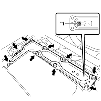
  1. Remove the 9 bolts and inverter cover.
    NOTICE:
    Make sure to pull the inverter cover straight up, as a connector is connected to the bottom of the cover.


    A248468E02
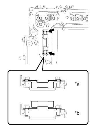
  1. Install the high voltage fuse with the 2 bolts.
    Text in Illustration 
    *a
    CORRECT
    *b
    INCORRECT

    Torque:
    4.0 N*m{ 41 kgf*cm , 35 in.*lbf }

    NOTICE:
    1. Be sure to use a torque wrench to tighten the bolts.
    2. The fuse should be installed with its orientation as shown in the illustration.

  1. Temporarily install the inverter cover with the 9 bolts to prevent any foreign objects or water from entering the inverter with converter assembly.


2. INSTALL MOTOR CABLE BRACKET
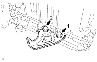
  1. Temporarily install the motor cable bracket with the 2 bolts.


    A215782E01
  1. Tighten the 2 bolts in the order shown in the illustration.

    Torque:
    8.0 N*m{ 82 kgf*cm , 71 in.*lbf }


3. INSTALL INVERTER WITH CONVERTER ASSEMBLY

CAUTION:
Wear insulating gloves.


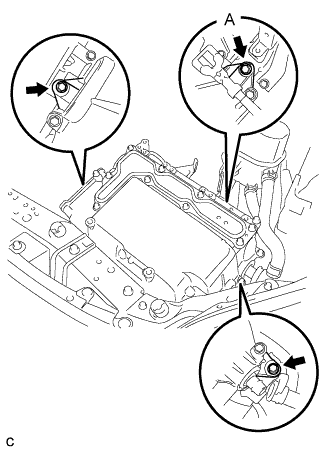
    A214665E02
  1. Temporarily install the inverter with converter assembly with the 3 bolts.

    NOTICE:
    1. Since the inverter with converter assembly is very heavy, 2 people are needed to install the inverter with converter assembly. When installing the inverter with converter assembly, do not damage the parts around it.
    2. To prevent damage, do not hold the inverter with converter assembly by the connectors.
    3. To prevent damage due to static electricity, do not touch the terminals of the disconnected connectors.

  1. Tighten bolt A.

    Torque:
    12 N*m{ 122 kgf*cm , 8 ft.*lbf }

  1. Tighten the 2 bolts.

    Torque:
    12 N*m{ 122 kgf*cm , 8 ft.*lbf }


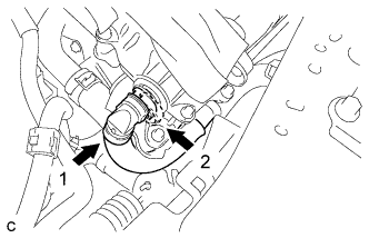
4. CONNECT WATER HOSE


    A214662E01
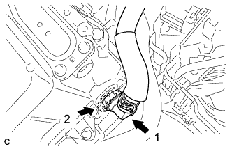
  1. Connect the water hose to the inverter with converter assembly and lock the hose with the retainer.
    NOTICE:
    1. Insert the retainer until a click sound is heard.
    2. Pull on the hose to confirm that the hose is securely connected.
    3. If there is foreign matter on the union or the O-ring, clean it with water and finger scouring.


    A214664E01
  1. Connect the water hose to the inverter with converter assembly and lock the hose with the retainer.

    NOTICE:
    1. Insert the retainer until a click sound is heard.
    2. Pull on the hose to confirm that the hose is securely connected.
    3. If there is foreign matter on the union or the O-ring, clean it with water and finger scouring.


5. CONNECT NO. 2 ENGINE ROOM WIRE
  1. Disconnect the No. 2 engine room wire from the protector.

  1. Connect the No. 2 engine room wire with the bolt and 2 claws.

    Torque:
    8.3 N*m{ 85 kgf*cm , 73 in.*lbf }

    NOTICE:
    Pass the No. 2 engine room wire under the two cooling hoses that pass beside the inverter.

  1. Install the No. 1 relay block cover and 2 clamps.

  1. Install the relay block cover.


6. REMOVE INVERTER COVER

CAUTION:
Wear insulating gloves.

  1. Remove the 9 bolts and inverter cover.

    NOTICE:
    Make sure to pull the inverter cover straight up, as a connector is connected to the bottom of the cover.


7. CONNECT NO. 2 ENGINE WIRE

CAUTION:
Wear insulating gloves.

NOTICE:
Do not allow any foreign objects or water to enter the inverter with converter assembly.


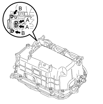
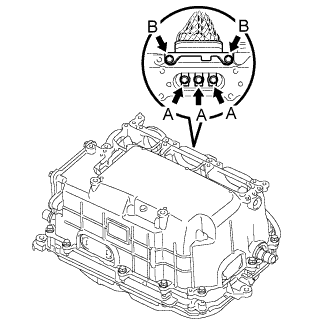
    A248444E01
  1. Temporarily install the No. 2 engine wire (high voltage cables of the air conditioning) and 4 bolts to the inverter assembly by hand.

  1. Fully tighten the 4 bolts.

    Torque:
    Bolt A:
    8.0 N*m{ 82 kgf*cm , 71 in.*lbf }
    Bolt B:
    9.2 N*m{ 94 kgf*cm , 81 in.*lbf }

    NOTICE:
    Be sure to use a torque wrench to tighten the bolts.

  1. Connect the harness clamp.


8. CONNECT MOTOR CABLE

CAUTION:
Wear insulating gloves.

NOTICE:
Do not allow any foreign objects or water to enter the inverter with converter assembly.


    A248443E01
  1. Temporarily install the high voltage cable of the motor (MG2) and 5 bolts to the inverter assembly by hand.

  1. Fully tighten the 5 bolts.

    Torque:
    Bolt A:
    8.0 N*m{ 82 kgf*cm , 71 in.*lbf }
    Bolt B:
    9.2 N*m{ 94 kgf*cm , 81 in.*lbf }

    NOTICE:
    Be sure to use a torque wrench to tighten the bolts.

  1. Connect the harness clamp.


9. CONNECT GENERATOR CABLE

CAUTION:
Wear insulating gloves.

NOTICE:
Do not allow any foreign objects or water to enter the inverter with converter assembly.


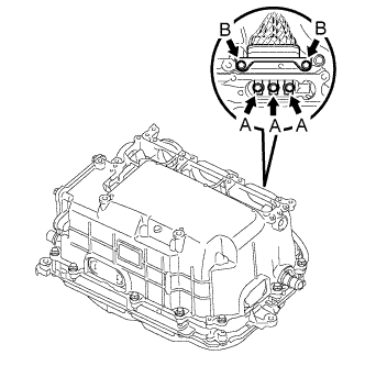
    A248442E01
  1. Temporarily install the high voltage cable of the generator cable (MG1) and 5 bolts to the inverter assembly by hand.

  1. Fully tighten the 5 bolts.

    Torque:
    Bolt A:
    8.0 N*m{ 82 kgf*cm , 71 in.*lbf }
    Bolt B:
    9.2 N*m{ 94 kgf*cm , 81 in.*lbf }

    NOTICE:
    Be sure to use a torque wrench to tighten the bolts.


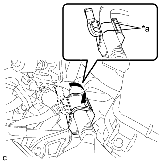
    A215780E02
  1. Install the generator cable and cover.
    Text in Illustration 
    *a
    Align Mark

    NOTICE:
    Close the cover so that the matchmarks are not visible.


10. CONNECT FRAME WIRE

CAUTION:
Wear insulating gloves.

NOTICE:
  1. Make sure that the interlock is fully engaged.
  2. Do not allow any foreign objects or water to enter the inverter with converter assembly.


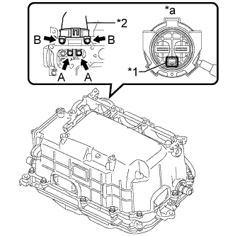
    A248445E01
  1. Temporarily install the frame wire (high voltage cables of the hybrid battery) and 4 bolts to the inverter assembly by hand.
    Text in Illustration 
    *1
    Interlock
    *2
    High voltage cables of the hybrid battery
    *a
    Front view of frame wire connector

  1. Fully tighten the 4 bolts.

    Torque:
    Bolt A:
    8.0 N*m{ 82 kgf*cm , 71 in.*lbf }
    Bolt B:
    9.2 N*m{ 94 kgf*cm , 81 in.*lbf }

    NOTICE:
    1. Be sure to use a torque wrench to tighten the bolts.
    2. Make sure that the interlock are fully engaged.

  1. Connect the 2 harness clamps.


11. CHECK HIGH VOLTAGE CABLE CONNECTION

CAUTION:
Wear insulating gloves.

NOTICE:
Do not allow any foreign objects or water to enter the inverter with converter assembly.


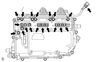
    A214667
  1. Check that each connector and terminal is firmly installed.

    NOTICE:
    Make sure that the bolts are fully tightened.


12. INSTALL INVERTER COVER

CAUTION:
Wear insulating gloves.

NOTICE:
  1. Make sure that the interlock is fully engaged.
  2. Do not allow any foreign objects or water to enter the inverter with converter assembly.


    A231540E01
  1. Install the inverter cover with the 9 bolts to the inverter with converter assembly.
    Text in Illustration 
    *1
    Interlock

    Torque:
    11 N*m{ 112 kgf*cm , 8 ft.*lbf }


13. INSTALL ENGINE ROOM MAIN WIRE

NOTICE:
  1. Make sure that the connectors are fully engaged.
  2. Do not allow any foreign objects or water to enter the inverter with converter assembly.

  1. Install the bolt, clamp and clip, and connect the engine room main wire.

    Torque:
    12 N*m{ 122 kgf*cm , 9 ft.*lbf }

  1. Install the bolt.

    Torque:
    12 N*m{ 122 kgf*cm , 9 ft.*lbf }


    A214645
  1. Connect the engine wire to the engine room main wire.
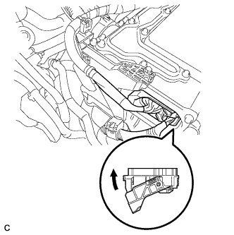


    A214648
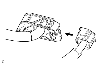
  1. Connect the connector to the inverter with converter assembly and lock the connector with the lock lever.


14. INSTALL NO. 1 INVERTER BRACKET


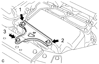
    A248080E01
  1. Temporarily install the No. 1 inverter bracket with the 3 bolts.

  1. Tighten the 3 bolts in the order shown in the illustration.

    Torque:
    14 N*m{ 138 kgf*cm , 10 ft.*lbf }


15. INSTALL SERVICE PLUG GRIP
(Click here).


16. ADD COOLANT (for Inverter)

NOTICE:
  1. Do not reuse the drained coolant because it may contain foreign objects.
  2. If the vehicle is driven with air in the inverter cooling system, damage may occur and the following DTCs may be stored.

    DTC No.
    Detection Item
    P0A01-726
    Motor Electronics Coolant Temperature Sensor Circuit Range / Performance
    P0A04-725
    Motor Electronics Coolant Temperature Sensor Circuit Intermittent
    P0A08-264
    DC / DC Converter Status Circuit
    P0A78-284
    Drive Motor "A" Inverter Performance
    P0A78-286
    Drive Motor "A" Inverter Performance
    P0A7A-322
    Generator Inverter Performance
    P0A7A-324
    Generator Inverter Performance
    P0A93-346
    Inverter Cooling System Performance
    P0A94-553
    DC / DC Converter Performance
    P0A94-557
    DC / DC Converter Performance
    P0AEE-277
    Motor Inverter Temperature Sensor "A" Circuit Range / Performance
    P0AF1-276
    Drive Motor Inverter Temperature Sensor "A" Circuit Intermittent / Erratic
    P0BCD-315
    Generator Inverter Temperature Sensor Circuit Range / Performance
    P0BD0-314
    Generator Inverter Temperature Sensor Circuit Intermittent / Erratic
    P0C39-626
    DC / DC Converter Temperature Sensor "A" Range / Performance
    P0C3C-625
    DC / DC Converter Temperature Sensor "A" Intermittent / Erratic
    P0C3E-628
    DC / DC Converter Temperature Sensor "B" Range / Performance
    P0C41-627
    DC / DC Converter Temperature Sensor "B" Intermittent / Erratic
    P0C73-776
    Motor Electronics Coolant Pump "A" Control Performance


    A248471
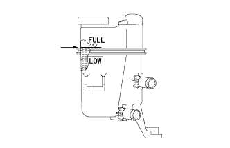
  1. Slowly pour coolant into the reserve tank until it reaches the full line.

    Coolant quantity:
    2.1 liters (2.2 US qts, 1.8 Imp. qts.)

  1. When using the intelligent tester:

    1. Connect the intelligent tester to the DLC3.

    2. Turn the power switch on (IG).

    3. Enter the following menus: Powertrain / Hybrid Control / Active Test / Activate the Water Pump.

    4. Keep the coolant at the full line in the reserve tank to compensate for the drop in coolant level when the air bleeds.

      Standard:
      Air bleeding from the inverter cooling system is completed when the noise made by the inverter water pump assembly becomes smaller and the circulation of coolant in the reserve tank improves.

      HINT:
      Loud noise made by the inverter water pump assembly and poor circulation of coolant in the reserve tank indicates that there is air in the cooling system.

  1. When not using the intelligent tester:

    1. Turn the power switch on (READY). [*1]

    2. Turn the power switch off and add coolant to the full line because the coolant level drops as the air bleeds. [*2]

      NOTICE:
      1. Be sure to turn the power switch off before adding SLLC.
      2. Do not work on the components in the engine compartment while the vehicle is in the READY-on state because the engine is in intermittent operation.

    3. Repeat steps [*1] and [*2] until air bleeding from the cooling system is completed.

      Standard:
      Air bleeding from the inverter cooling system is completed when the noise made by the inverter water pump assembly becomes smaller and the circulation of coolant in the reserve tank improves.

      HINT:
      Loud noise made by the inverter water pump assembly and poor circulation of coolant in the reserve tank indicates that there is air in the cooling system.

  1. After the air is completely bled from the cooling system, tighten the reserve tank cap.


    A248471
  1. Add coolant to the full line of the reserve tank.


17. INSPECT FOR COOLANT LEAK (for Inverter)
  1. Remove the reserve tank cap.

    CAUTION:
    To avoid the danger of being burned, do not remove the reserve tank cap while the coolant for the inverter is still hot.


    A248084
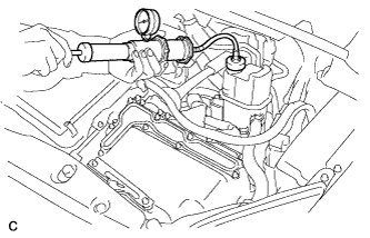
  1. Install a radiator cap tester.

  1. Pump the radiator cap tester to 122 kPa (1.2 kgf/ cm2, 18 psi), and then check that the pressure does not drop.

    HINT:
    If the pressure drops, check the hoses, radiator, inverter water pump assembly, inverter with converter, and hybrid vehicle transaxle assembly for leaks.

  1. Reinstall the reserve tank cap.


18. INSTALL NO. 1 ENGINE UNDER COVER


19. INSTALL INVERTER COVER ASSEMBLY LH (w/ Cover)
  1. Engage the claw and install the inverter cover assembly LH.

  1. Install the 2 clips.


20. INSTALL RADIATOR SUPPORT OPENING COVER
  1. Install the radiator support opening cover with the 9 clips.