INVERTER WITH CONVERTER > REMOVAL |
| 1. PRECAUTION |
| 2. REMOVE SERVICE PLUG GRIP |
| 3. REMOVE NO. 1 ENGINE UNDER COVER |
| 4. DRAIN COOLANT (for Inverter) |
Remove the reserve tank cap.
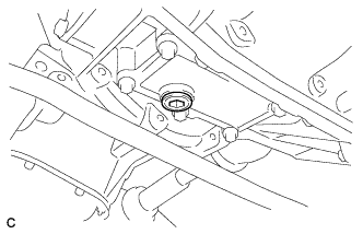 |
Using a hexagon wrench (10 mm), remove the drain plug indicated in the illustration and drain the coolant.
Install the plug with a new gasket.
| 5. REMOVE INVERTER COVER ASSEMBLY LH (w/ Cover) |
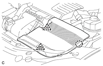 |
Remove the 2 clips
Disengage the claw and remove the inverter cover assembly LH.
| 6. REMOVE RADIATOR SUPPORT OPENING COVER |
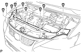 |
Remove the 9 clips and radiator support opening cover.
| 7. REMOVE NO. 1 INVERTER BRACKET |
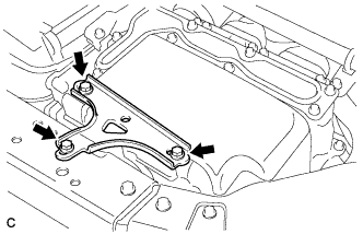 |
Remove the 3 bolts and No. 1 inverter bracket.
| 8. DISCONNECT ENGINE ROOM MAIN WIRE |
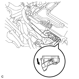 |
Raise the lock lever and disconnect the inverter with converter connector.
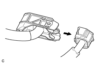 |
Disconnect the engine wire from the engine room main wire.
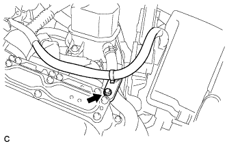 |
Remove the bolt.
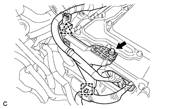 |
Remove the bolt, clamp and clip, and disconnect the engine room main wire.
| 9. REMOVE INVERTER COVER |
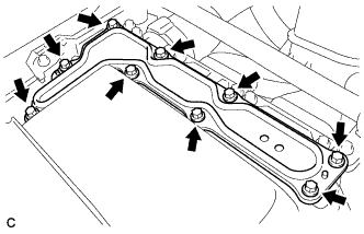 |
Remove the 9 bolts and inverter cover.
| 10. CHECK TERMINAL VOLTAGE |
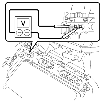 |
Using a voltmeter, measure the voltage between the terminals of the 2 phase connectors.
| 11. DISCONNECT FRAME WIRE |
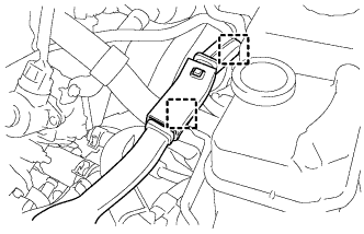 |
Disconnect the 2 harness clamps.
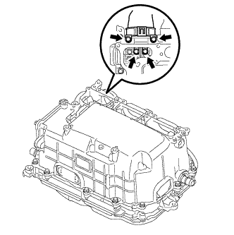 |
Remove the 4 bolts, and disconnect the frame wire (high voltage cables of the hybrid battery) from the inverter with converter assembly.
| 12. DISCONNECT GENERATOR CABLE |
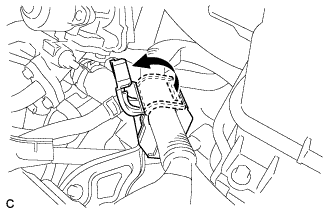 |
Turn back the wire harness cover and release the cable.
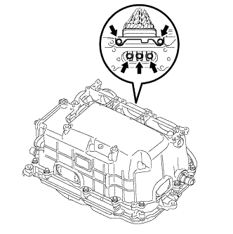 |
Remove the 5 bolts, and disconnect the high voltage cables of the generator cable (MG1) from the inverter with converter assembly.
| 13. DISCONNECT MOTOR CABLE |
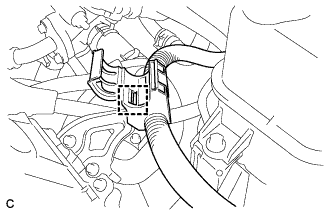 |
Disconnect the harness clamp.
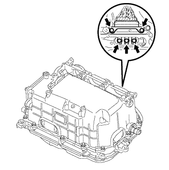 |
Remove the 5 bolts, and disconnect the high voltage cables of the motor cable (MG2) from the inverter with converter assembly.
| 14. DISCONNECT NO. 2 ENGINE WIRE |
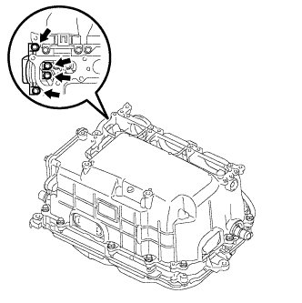 |
Remove the 4 bolts, and disconnect the No. 2 engine wire (high voltage cables for the air conditioning compressor) from the inverter with converter assembly.
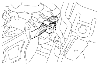 |
Disconnect the harness clamp.
| 15. INSTALL INVERTER COVER |
|
Temporarily install the inverter cover with the 9 bolts to prevent any foreign objects or water from entering the inverter with converter assembly.
| 16. DISCONNECT NO. 2 ENGINE ROOM WIRE |
Remove the relay block cover.
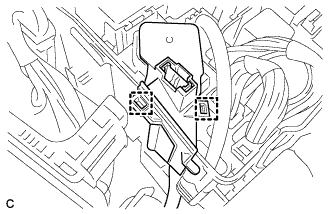 |
Release the 2 clamps, and remove the No. 1 relay block cover.
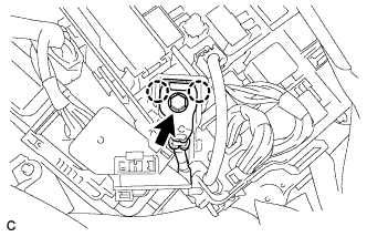 |
Remove the bolt from the No. 2 engine room wire.
Release the 2 claws, and disconnect the No. 2 engine room wire.
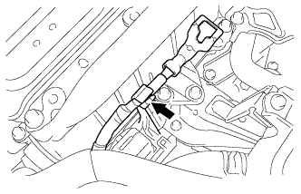 |
Connect the No. 2 engine room wire to the protector.
| 17. DISCONNECT WATER HOSE |
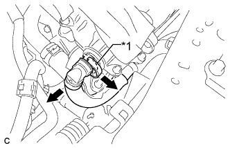 |
Release the retainer and disconnect the water hose from the inverter with converter assembly.
| *1 | Retainer |
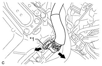 |
Release the retainer and disconnect the water hose from the inverter with converter assembly.
| *1 | Retainer |
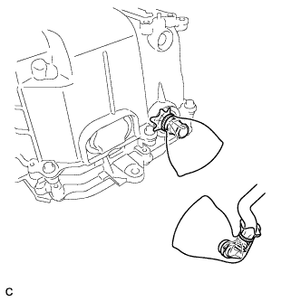 |
Disconnect the coolant hose from the inverter with converter assembly. Put a piece of cloth in the pipe and in the disconnected hose or cover the pipe and hose with plastic bags as shown in the illustration, so that foreign matter doesn't stick to the union or the inside of the connector and to prevent coolant from spilling near the inverter with converter assembly.
| 18. REMOVE INVERTER WITH CONVERTER ASSEMBLY |
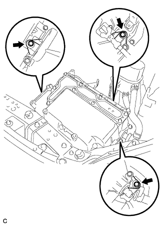 |
Remove the 3 bolts and inverter with converter assembly.
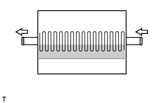 |
Even after the coolant is drained, coolant remains in the inverter due to its internal structure. Therefore, seal or cover the pipes when removing the inverter so that coolant does not spill out.
| 19. REMOVE MOTOR CABLE BRACKET |
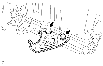 |
Remove the 2 bolts and motor cable bracket.
| 20. REMOVE HIGH VOLTAGE FUSE |
|
Remove the 9 bolts and inverter cover.
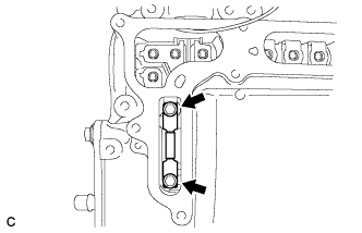 |
Remove the 2 bolts and high voltage fuse from the inverter with converter assembly.
|
Temporarily install the inverter cover with the 9 bolts to prevent any foreign objects or water from entering the inverter with converter assembly.
