HV RELAY ASSEMBLY > INSPECTION |
| 1. INSPECT HYBRID BATTERY JUNCTION BLOCK ASSEMBLY |
Inspect SMRB
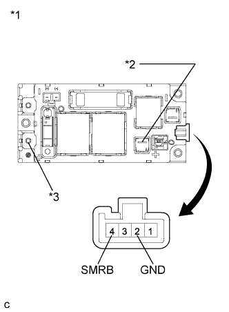 |
Measure the resistance according to the value(s) in the table below.
| Tester Connection | Condition | Specified Condition |
| (+) connector - (+) terminal | Auxiliary battery voltage is not applied between terminals 4 (SMRB) and 2 (GND) | 10 kΩ or higher |
| (+) connector - (+) terminal | Auxiliary battery voltage is applied between terminals 4 (SMRB) and 2 (GND) | Below 1 Ω |
| *1 | Hybrid Battery Junction Block Assembly |
| *2 | (+) Connector |
| *3 | (+) Terminal |
Measure the resistance according to the value(s) in the table below.
| Tester Connection | Condition | Specified Condition |
| 4 (SMRB) - 2 (GND) | -40 to 80°C (-40 to 176°F) | 19.0 to 35.5 Ω |
Inspect SMRG
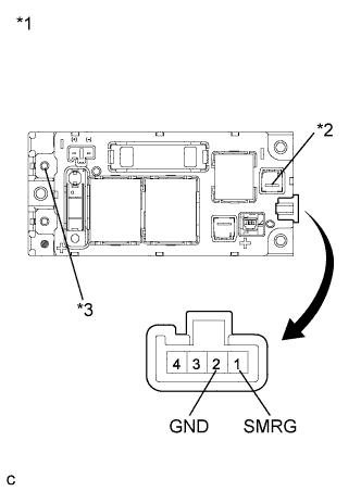 |
Measure the resistance according to the value(s) in the table below.
| Tester Connection | Condition | Specified Condition |
| (-) connector - (-) terminal | Auxiliary battery voltage is not applied between terminals 1 (SMRG) and 2 (GND) | 10 kΩ or higher |
| (-) connector - (-) terminal | Auxiliary battery voltage is applied between terminals 1 (SMRG) and 2 (GND) | Below 1 Ω |
| *1 | Hybrid Battery Junction Block Assembly |
| *2 | (-) Connector |
| *3 | (-) Terminal |
Measure the resistance according to the value(s) in the table below.
| Tester Connection | Condition | Specified Condition |
| 1 (SMRG) - 2 (GND) | -40 to 80°C (-40 to 176°F) | 19.0 to 35.5 Ω |
Inspect SMRP and system main resister
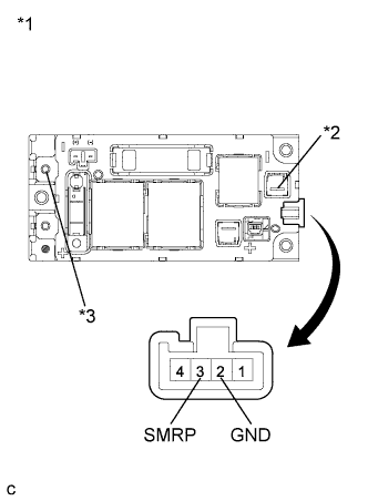 |
Measure the resistance according to the value(s) in the table below.
| Tester Connection | Condition | Specified Condition |
| (-) connector - (-) terminal | Auxiliary battery voltage is not applied between terminals 3 (SMRP) and 2 (GND) | 10 kΩ or higher |
| (-) connector - (-) terminal | Auxiliary battery voltage is applied between terminals 3 (SMRP) and 2 (GND) | 28.5 to 31.5 Ω |
| *1 | Hybrid Battery Junction Block Assembly |
| *2 | (-) Connector |
| *3 | (-) Terminal |
Measure the resistance according to the value(s) in the table below.
| Tester Connection | Condition | Specified Condition |
| 3 (SMRP) - 2 (GND) | -40 to 80°C (-40 to 176°F) | 112 to 274 Ω |
