STEERING COLUMN ASSEMBLY > INSTALLATION |
| 1. INSPECT STEERING COLUMN ASSEMBLY |
Inspect the bushings.
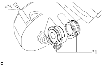 |
Check that the 2 bushings are securely installed to the steering column assembly.
| *1 | Bushing |
Check the 2 bushings for deformation and damage.
If the bushings are deformed or damaged, replace the steering column assembly with a new one.
Inspect the capsules.
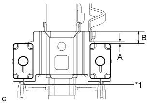 |
Check that the 2 capsules are securely installed to the steering column assembly as shown in the illustration.
| A | B |
| 2 mm (0.0787 in.) | 17 mm (0.669 in.) |
| *1 | Capsule |
Check the 2 capsules for deformation and damage.
If either of the capsules is deformed, loose, missing or damaged, replace the steering column assembly with a new one.
| 2. INSTALL NO. 2 STEERING INTERMEDIATE SHAFT ASSEMBLY |
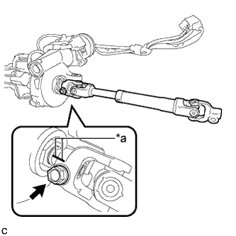 |
Align the matchmarks on the No. 2 steering intermediate shaft assembly and steering column assembly to install the No. 2 steering intermediate shaft assembly.
| *a | Matchmark |
Install the bolt.
| 3. ALIGN FRONT WHEELS FACING STRAIGHT AHEAD |
| 4. INSTALL STEERING POST ASSEMBLY (for LHD) |
Install the steering post assembly with the bolt and 2 nuts.
Engage the wire harness clamps to the steering post assembly.
Engage the 2 wire harness clamps.
Connect the connector to the power steering ECU assembly.
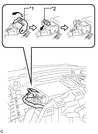 |
Connect the connector to the power steering ECU assembly.
| *1 | Lock Lever |
| *2 | Lock of Lock Lever |
| 5. INSTALL STEERING POST ASSEMBLY (for RHD) |
Install the steering post assembly with the bolt and 2 nuts.
Engage the wire harness clamps to the steering post assembly.
Engage the 2 wire harness clamps.
| 6. CONNECT NO. 2 STEERING INTERMEDIATE SHAFT ASSEMBLY |
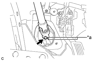 |
Align the matchmarks on the No. 2 steering intermediate shaft assembly and steering intermediate shaft to connect the No. 2 steering intermediate shaft assembly to the steering intermediate shaft.
| *a | Matchmark |
Install the bolt.
| 7. INSTALL COLUMN HOLE COVER SILENCER SHEET |
Install the column hole cover silencer sheet with the 2 clips.
Install the floor carpet.
| 8. INSTALL NO. 1 AIR DUCT SUB-ASSEMBLY (for LHD) |
Engage the 2 claws to install the No. 1 air duct sub-assembly.
| 9. INSTALL STOP LIGHT SWITCH ASSEMBLY (for LHD) |
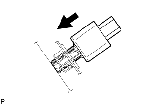 |
Insert the stop light switch assembly until the rod hits the pedal.
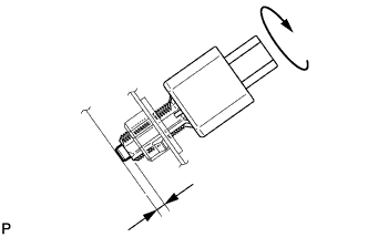 |
Make a quarter turn clockwise to install the stop light switch assembly.
Connect the connector.
Check the protrusion of the rod.
| 10. INSTALL LOWER NO. 1 INSTRUMENT PANEL AIRBAG ASSEMBLY (for LHD) |
| 11. INSTALL UPPER INSTRUMENT PANEL ASSEMBLY (for LHD) |
| 12. INSTALL NO. 2 AIR DUCT SUB-ASSEMBLY (for RHD) |
Engage the 2 claws to install the No. 2 air duct sub-assembly.
| 13. INSTALL BRAKE PEDAL SUPPORT ASSEMBLY (for RHD) |
| 14. INSTALL TURN SIGNAL SWITCH ASSEMBLY WITH SPIRAL CABLE SUB-ASSEMBLY |
Using pliers, expand the clamp.
While holding the clamp expanded, install the turn signal switch assembly with spiral cable sub-assembly to the steering post assembly and engage the claw.
Return the clamp to its original position.
Connect the connectors to the turn signal switch assembly with spiral cable sub-assembly.
| 15. INSTALL STEERING COLUMN COVER |
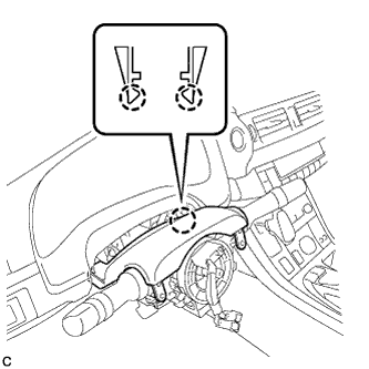 |
Engage the 2 claws to install the steering column cover (upper side).
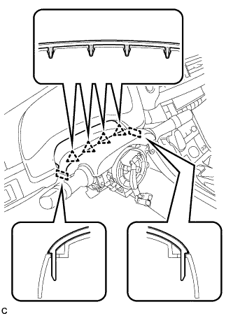 |
Engage the 4 clips and 2 guides to the steering column cover (upper side).
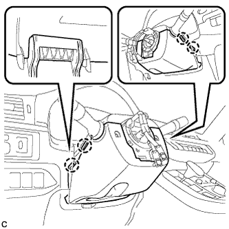 |
Engage the 4 claws to install the steering column cover (lower side).
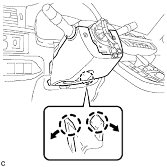 |
Engage the 2 claws.
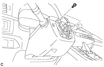 |
Install the 2 screws.
| 16. ALIGN FRONT WHEELS FACING STRAIGHT AHEAD |
| 17. ADJUST SPIRAL CABLE WITH SENSOR SUB-ASSEMBLY |
Check that the power switch is off.
Check that the cable is disconnected from the negative (-) auxiliary battery terminal.
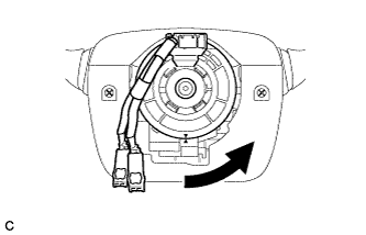 |
Rotate the spiral cable counterclockwise slowly by hand until it stops.
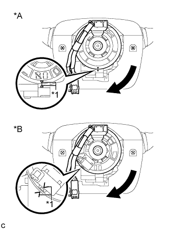 |
Rotate the spiral cable clockwise approximately 2.5 turns to align the marks.
| *A | w/o Steering Heater |
| *B | w/ Steering Heater |
| *1 | Alignment Mark |
| 18. INSTALL STEERING WHEEL ASSEMBLY |
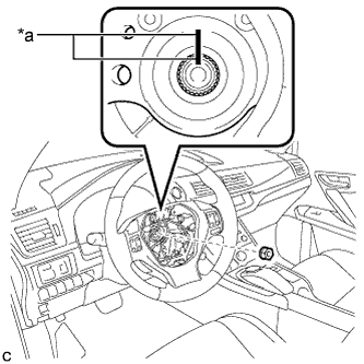 |
Install the steering wheel assembly aligning the matchmarks on the steering wheel assembly and steering main shaft.
| *a | Matchmark |
Install the steering wheel assembly set nut.
Connect the connectors to the spiral cable and steering wheel assembly.
| 19. CHECK STEERING WHEEL CENTER POINT |
| 20. INSTALL HORN BUTTON ASSEMBLY |
| 21. ROTATION ANGLE SENSOR VALUE INITIALIZATION AND TORQUE SENSOR ZERO POINT CALIBRATION |
