STEERING COLUMN ASSEMBLY > REMOVAL |
| 1. ALIGN FRONT WHEELS FACING STRAIGHT AHEAD |
| 2. REMOVE HORN BUTTON ASSEMBLY |
| 3. REMOVE STEERING WHEEL ASSEMBLY |
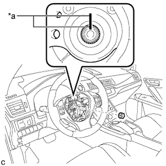 |
Remove the steering wheel assembly set nut.
| *a | Matchmark |
Put matchmarks on the steering wheel assembly and steering main shaft.
Disconnect the connectors from the spiral cable and steering wheel assembly.
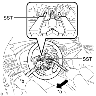 |
Using SST, remove the steering wheel assembly.
| *a | Turn |
| *b | Hold |
| 4. REMOVE STEERING COLUMN COVER |
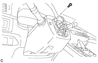 |
Remove the 2 screws.
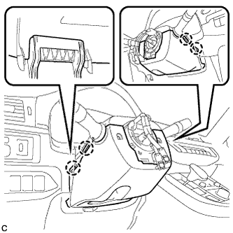 |
Push the right and left sides of the steering column cover (lower side) to disengage the 4 claws.
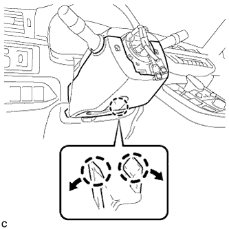 |
Insert fingers into the opening of the tilt lever of the steering column cover (lower side) to disengage the 2 claws and remove the steering column cover (lower side).
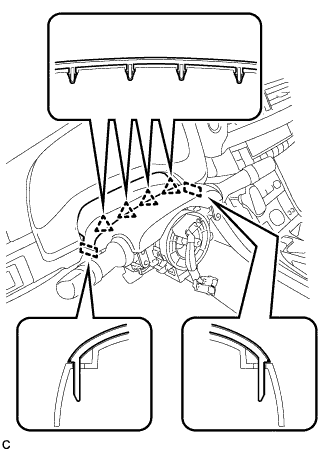 |
Disengage the 4 clips and 2 guides from the steering column cover (upper side).
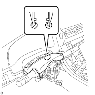 |
Disengage the 2 claws to remove the steering column cover (upper side).
| 5. REMOVE TURN SIGNAL SWITCH ASSEMBLY WITH SPIRAL CABLE SUB-ASSEMBLY |
Disconnect the connectors from the turn signal switch assembly with spiral cable sub-assembly.
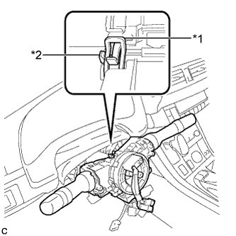 |
Using pliers, expand the clamp.
| *1 | Clamp |
| *2 | Claw |
While holding the clamp expanded, raise the claw using a screwdriver to disengage it, and then remove the turn signal switch assembly with spiral cable sub-assembly from the steering post assembly.
| 6. REMOVE UPPER INSTRUMENT PANEL ASSEMBLY (for LHD) |
| 7. REMOVE LOWER NO. 1 INSTRUMENT PANEL AIRBAG ASSEMBLY (for LHD) |
| 8. REMOVE STOP LIGHT SWITCH ASSEMBLY (for LHD) |
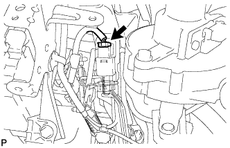 |
Disconnect the connector.
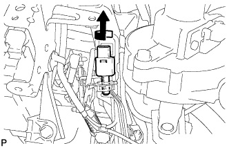 |
Turn the stop light switch assembly counterclockwise and remove it.
| 9. REMOVE NO. 1 AIR DUCT SUB-ASSEMBLY (for LHD) |
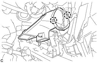 |
Disengage the 2 claws to remove the No. 1 air duct sub-assembly.
| 10. REMOVE BRAKE PEDAL SUPPORT ASSEMBLY (for RHD) |
| 11. REMOVE NO. 2 AIR DUCT SUB-ASSEMBLY (for RHD) |
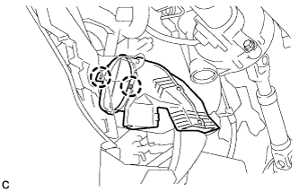 |
Disengage the 2 claws to remove the No. 2 air duct sub-assembly.
| 12. REMOVE COLUMN HOLE COVER SILENCER SHEET |
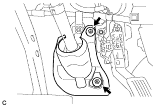 |
Turn back the floor carpet.
Remove the 2 clips and column hole cover silencer sheet.
| 13. SEPARATE NO. 2 STEERING INTERMEDIATE SHAFT ASSEMBLY |
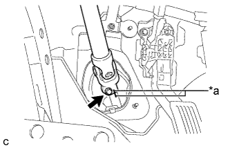 |
Put matchmarks on the No. 2 steering intermediate shaft assembly and steering intermediate shaft.
| *a | Matchmark |
Remove the bolt.
Separate the No. 2 steering intermediate shaft assembly from the steering intermediate shaft.
| 14. REMOVE STEERING POST ASSEMBLY (for LHD) |
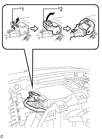 |
Disconnect the connector from the power steering ECU assembly.
| *1 | Lock of Lock Lever |
| *2 | Lock Lever |
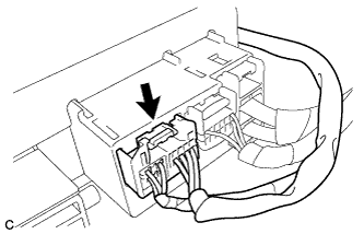 |
Disconnect the connector from the power steering ECU assembly.
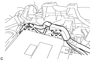 |
Disengage the 2 wire harness clamps.
Disengage the wire harness clamps from the steering post assembly.
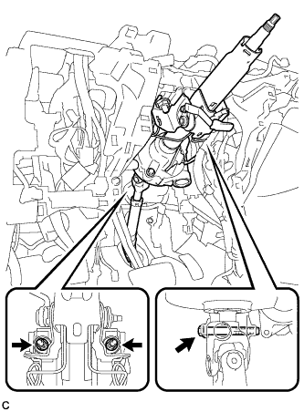 |
Remove the bolt, 2 nuts and steering post assembly.
| 15. REMOVE STEERING POST ASSEMBLY (for RHD) |
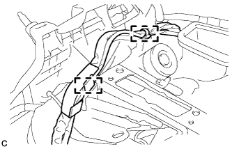 |
Disengage the 2 wire harness clamps.
Disengage the wire harness clamps from the steering post assembly.
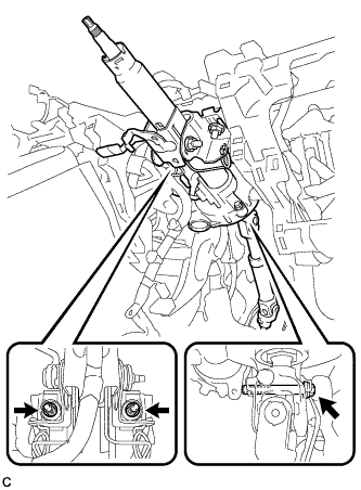 |
Remove the bolt, 2 nuts and steering post assembly.
| 16. REMOVE NO. 2 STEERING INTERMEDIATE SHAFT ASSEMBLY |
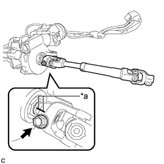 |
Put matchmarks on the No. 2 steering intermediate shaft assembly and steering column assembly.
| *a | Matchmark |
Remove the bolt and No. 2 steering intermediate shaft assembly from the steering column assembly.
