DTC P0136 Oxygen Sensor Circuit Malfunction (Bank 1 Sensor 2) |
DTC P0137 Oxygen Sensor Circuit Low Voltage (Bank 1 Sensor 2) |
DTC P0138 Oxygen Sensor Circuit High Voltage (Bank 1 Sensor 2) |
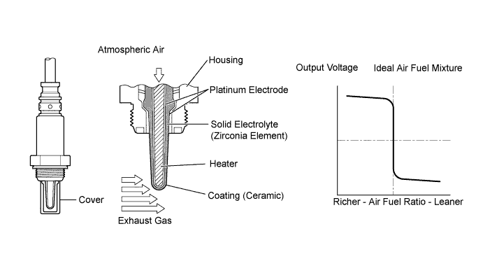
| DTC No. | DTC Detection Condition | Trouble Area |
| P0136* | Abnormal voltage output:
|
|
| P0137 | Low voltage (open):
|
|
| P0138* | High voltage (short):
|
|
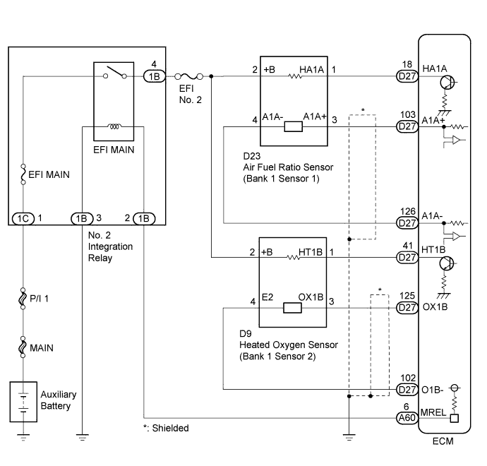
| Active Air Fuel Ratio Control |
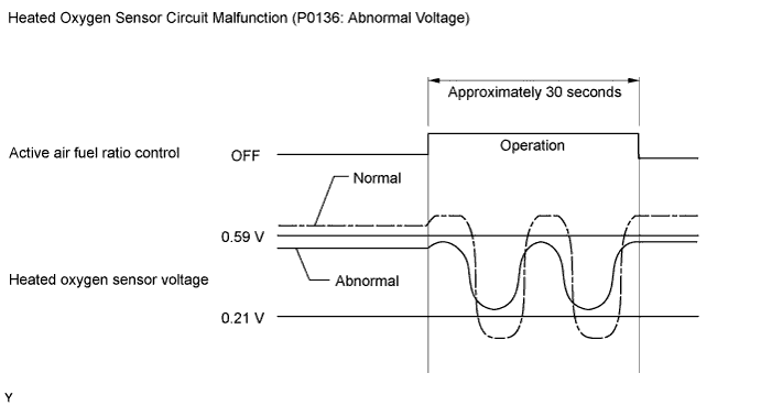
| Abnormal Voltage Output of Heated Oxygen Sensor (DTC P0136) |
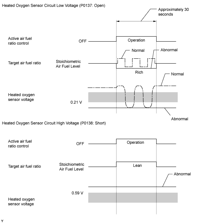
| Open or Short in Heated Oxygen Sensor Circuit (DTCs P0137 or P0138) |
| Active air fuel ratio control | Performing |
| Active air fuel ratio control begins when all of the following conditions are met: | - |
| Auxiliary battery voltage | 11 V or higher |
| Engine coolant temperature | 75°C (167°F) or higher |
| Idling | OFF |
| Engine speed | Less than 4000 rpm |
| Air fuel ratio sensor status | Activated |
| Fuel system status | Closed loop |
| Engine load | 10 to 70% |
| Either of the following conditions is met: | 1 or 2 |
| 1. Both of following conditions met | (a) and (b) |
| (a) Commanded air fuel ratio | 14.3 or less |
| (b) Heated oxygen sensor voltage | 0.21 to 0.59 V |
| 2. Both of following conditions met | (c) and (d) |
| (c) Commanded air fuel ratio | 14.9 or more |
| (d) Heated oxygen sensor voltage | 0.21 to 0.59 V |
| Both of following conditions met | (a) and (b) |
| (a) Commanded air fuel ratio | 14.3 or less |
| (b) Heated oxygen sensor voltage | Below 0.21 V |
| Both of following conditions met | (a) and (b) |
| (a) Commanded air fuel ratio | 14.9 or more |
| (b) Heated oxygen sensor voltage | Higher than 0.59 V |
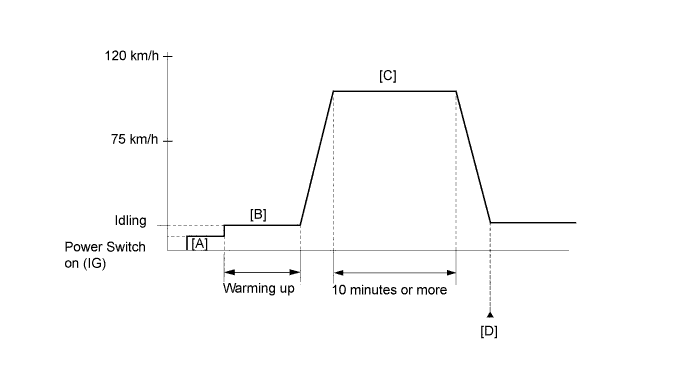
| Tester Display | Description |
| NORMAL |
|
| ABNORMAL |
|
| INCOMPLETE |
|
| UNKNOWN |
|
| Tester Display (Sensor) | Injection Volume | Status | Voltage |
| AFS Voltage B1S1 (Air fuel ratio) | +12% | Rich | Less than 3.1 V |
| AFS Voltage B1S1 (Air fuel ratio) | -12% | Lean | Higher than 3.4 V |
| O2S B1S2 (Heated oxygen) | +12% | Rich | Higher than 0.55 V |
| O2S B1S2 (Heated oxygen) | -12% | Lean | Less than 0.4 V |
| Case | Air Fuel Ratio Sensor (Sensor 1) Output Voltage | Heated Oxygen Sensor (Sensor 2) Output Voltage | Main Suspected Trouble Area |
| 1 | 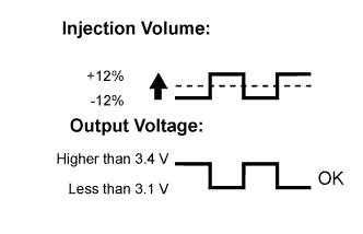 | 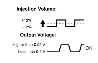 | - |
| 2 | 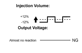 | |
|
| 3 | | 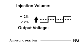 |
|
| 4 | | |
|
| 1.READ DTC OUTPUT (DTC P0136, P0137 OR P0138) |
Connect the intelligent tester to the DLC3.
Turn the power switch on (IG).
Turn the tester on.
Enter the following menus: Powertrain / Engine and ECT / DTC.
Read the DTCs.
| Result | Proceed to |
| DTC P0138 is output | A |
| DTC P0137 is output | B |
| DTC P0136 is output | C |
| P0136, P0137 or P0138 and other DTCs are output | D |
|
| ||||
|
| ||||
|
| ||||
| A | |
 |
| 2.READ VALUE USING INTELLIGENT TESTER (O2S B1S2) |
Connect the intelligent tester to the DLC3.
Turn the power switch on (IG).
Turn the tester on.
Put the engine in inspection mode (maintenance mode) (Click here).
Start the engine.
Enter the following menus: Powertrain / Engine and ECT / Data List / All Data / O2S B1S2.
Read the heated oxygen sensor output voltage while idling.
| Result | Proceed to |
| 1.0 V or higher | A |
| Below 1.0 V | B |
|
| ||||
| A | |
|
| 3.INSPECT HEATED OXYGEN SENSOR (CHECK FOR SHORT) |
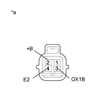 |
Disconnect the heated oxygen sensor connector.
Measure the resistance according to the value(s) in the table below.
| Tester Connection | Condition | Specified Condition |
| 2 (+B) - 4 (E2) | Always | 10 kΩ or higher |
| 2 (+B) - 3 (OX1B) | Always | 10 kΩ or higher |
| *a | Component without harness connected (Heated Oxygen Sensor (Sensor 2)) |
|
| ||||
| OK | |
|
| 4.CHECK HARNESS AND CONNECTOR (CHECK FOR SHORT) |
Turn the power switch off and wait for 5 minutes or more.
Disconnect the ECM connector.
Measure the resistance according to the value(s) in the table below.
| Tester Connection | Condition | Specified Condition |
| D27-41 (HT1B) - D27-125 (OX1B) | Always | 10 kΩ or higher |
|
| ||||
| OK | ||
 | ||
| ||
| 5.PERFORM ACTIVE TEST USING INTELLIGENT TESTER (CONTROL THE INJECTION VOLUME) |
Connect the intelligent tester to the DLC3.
Turn the power switch on (IG).
Turn the tester on.
Put the engine in inspection mode (maintenance mode) (Click here).
Start the engine and warm it up.
Enter the following menus: Powertrain / Engine and ECT / Active Test / Control the Injection Volume / All Data / AFS Voltage B1S1 and O2S B1S2.
Change the fuel injection volume using the tester and monitor the voltage output of air fuel ratio and heated oxygen sensors displayed on the tester.
| Tester Display (Sensor) | Voltage Variation | Proceed to |
| AFS Voltage B1S1 (Air fuel ratio) | Alternates between higher and below 3.3 V | OK |
| Remains at higher than 3.3 V | NG | |
| Remains at below 3.3 V | NG |
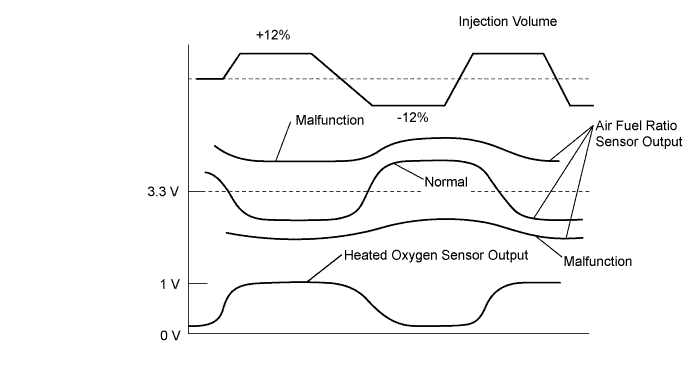
|
| ||||
| OK | |
|
| 6.INSPECT AIR FUEL RATIO SENSOR |
Connect the intelligent tester to the DLC3.
Turn the power switch on (IG).
Turn the tester on.
Clear the DTCs (Click here).
Put the engine in inspection mode (maintenance mode) (Click here).
Start the engine and warm it up until the engine coolant temperature reaches 75°C (167°F) or more.
Drive the vehicle at 75 km/h (47 mph) or more for 10 minutes or more.
Stop the vehicle.
Enter the following menus: Powertrain / Engine and ECT / Data List / All Data / AFS Current B1S1.
Drive the vehicle at 75 km/h (47 mph) or more and decelerate the vehicle for 5 seconds or more. Perform this 3 times.
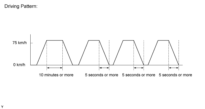
Read the value of the air fuel ratio sensor current while the fuel-cut operation is being performed.
|
| ||||
|
| ||||
| 7.PERFORM ACTIVE TEST USING INTELLIGENT TESTER (CONTROL THE INJECTION VOLUME) |
Connect the intelligent tester to the DLC3.
Turn the power switch on (IG).
Turn the tester on.
Put the engine in inspection mode (maintenance mode) (Click here).
Start the engine and warm it up.
Enter the following menus: Powertrain / Engine and ECT / Active Test / Control the Injection Volume / All Data / O2S B1S2.
Change the fuel injection volume using the tester, monitoring the voltage output of the heated oxygen sensor displayed on the tester.
|
| ||||
| OK | |
|
| 8.PERFORM ACTIVE TEST USING INTELLIGENT TESTER (CONTROL THE INJECTION VOLUME) |
Connect the intelligent tester to the DLC3.
Turn the power switch on (IG).
Turn the tester on.
Put the engine in inspection mode (maintenance mode) (Click here).
Start the engine and warm it up.
Enter the following menus: Powertrain / Engine and ECT / Active Test / Control the Injection Volume / All Data / AFS Voltage B1S1 and O2S B1S2.
Change the fuel injection volume using the tester and monitor the voltage output of air fuel ratio and heated oxygen sensors displayed on the tester.
| Tester Display (Sensor) | Voltage Variation | Proceed to |
| AFS Voltage B1S1 (Air fuel ratio) | Alternates between higher and below 3.3 V | OK |
| Remains at higher than 3.3 V | NG | |
| Remains at below 3.3 V | NG |
|
| ||||
| OK | |
|
| 9.PERFORM ACTIVE TEST USING INTELLIGENT TESTER (CONTROL THE EGR STEP POSITION) |
Connect the intelligent tester to the DLC3.
Turn the power switch on (IG).
Turn the tester on.
Put the engine in inspection mode (maintenance mode) (Click here).
Start the engine and warm it up until the engine coolant temperature reaches 75°C (167°F) or more.
Enter the following menus: Powertrain / Engine and ECT / Active Test / Control the EGR Step Position / Data List / All Data / Throttle Idle Position and MAP.
Confirm that the Throttle Idle Position is ON and check the engine idling condition and MAP values in the Data List while performing the Active Test.
| - | EGR Step Position (Active Test) | |
| 0 Steps | 0 to 30 Steps | |
| Idling condition | Steady idling | Idling changes from steady to rough idling or stalls |
| MAP (Data List) | MAP value is 20 to 40 kPa (150 to 300 mmHg) (EGR valve is fully closed) | MAP value is at least +10 kPa (75 mmHg) higher than when EGR valve is fully closed |
| Result | Proceed to |
| Outside of standard range | A |
| Within standard range | B |
|
| ||||
| A | |
|
| 10.INSPECT EGR VALVE ASSEMBLY |
Remove the EGR valve assembly (Click here).
Check if the EGR valve is stuck open.
|
| ||||
| OK | ||
| ||
| ||
| 11.CHECK EXHAUST GAS LEAK |
Check for exhaust gas leaks.
|
| ||||
| OK | |
|
| 12.INSPECT HEATED OXYGEN SENSOR (HEATER RESISTANCE) |
Inspect the heated oxygen sensor (Click here).
|
| ||||
| OK | |
|
| 13.CHECK HARNESS AND CONNECTOR (HEATED OXYGEN SENSOR - ECM) |
Disconnect the heated oxygen sensor connector.
Disconnect the ECM connector.
Measure the resistance according to the value(s) in the table below.
| Tester Connection | Condition | Specified Condition |
| D9-1 (HT1B) - D27-41 (HT1B) | Always | Below 1 Ω |
| D9-3 (OX1B) - D27-125 (OX1B) | Always | Below 1 Ω |
| D9-4 (E2) - D27-102 (O1B-) | Always | Below 1 Ω |
| D9-1 (HT1B) or D27-41 (HT1B) - Body ground | Always | 10 kΩ or higher |
| D9-3 (OX1B) or D27-125 (OX1B) - Body ground | Always | 10 kΩ or higher |
|
| ||||
| OK | |
|
| 14.REPLACE HEATED OXYGEN SENSOR |
Replace the heated oxygen sensor (Click here).
| NEXT | |
|
| 15.PERFORM CONFIRMATION DRIVING PATTERN |
Connect the intelligent tester to the DLC3.
Turn the power switch on (IG).
Turn the tester on.
Clear the DTCs (Click here).
Turn the power switch off and wait for at least 30 seconds.
Drive the vehicle in accordance with the driving pattern described in the Confirmation Driving Pattern.
| NEXT | |
|
| 16.CHECK WHETHER DTC OUTPUT RECURS (P0136, P0137 OR P0138) |
Enter the following menus: Powertrain / Engine and ECT / Utility / All Readiness.
Input the DTCs: P0136, P0137 or P0138.
Check the DTC judgment result is NORMAL. If it is INCOMPLETE, perform the drive pattern adding the vehicle speed.
| Result | Proceed to |
| ABNORMAL (DTC P0136, P0137 or P0138 is output) | A |
| NORMAL (DTC is not output) | B |
|
| ||||
| A | |
|
| 17.PERFORM ACTIVE TEST USING INTELLIGENT TESTER (CONTROL THE EGR STEP POSITION) |
Connect the intelligent tester to the DLC3.
Turn the power switch on (IG).
Turn the tester on.
Put the engine in inspection mode (maintenance mode) (Click here).
Start the engine and warm it up until the engine coolant temperature reaches 75°C (167°F) or higher.
Enter the following menus: Powertrain / Engine and ECT / Active Test / Control the EGR Step Position / Data List / All Data / Throttle Idle Position and MAP.
Confirm that the Throttle Idle Position is ON and check the engine idling condition and MAP values in the Data List while performing the Active Test.
| - | EGR Step Position (Active Test) | |
| 0 Steps | 0 to 30 Steps | |
| Idling condition | Steady idling | Idling changes from steady to rough idling or stalls |
| MAP (Data List) | MAP value is 20 to 40 kPa (150 to 300 mmHg) (EGR valve is fully closed) | MAP value is at least +10 kPa (75 mmHg) higher than when EGR valve is fully closed |
| Result | Proceed to |
| Outside of standard range | A |
| Within standard range | B |
|
| ||||
| A | |
|
| 18.INSPECT EGR VALVE ASSEMBLY |
Remove the EGR valve assembly (Click here).
Check if the EGR valve is stuck open.
|
| ||||
| OK | ||
| ||
| ||
| 19.REPLACE AIR FUEL RATIO SENSOR |
Replace the air fuel ratio sensor (Click here).
| NEXT | |
|
| 20.PERFORM CONFIRMATION DRIVING PATTERN |
Connect the intelligent tester to the DLC3.
Turn the power switch on (IG).
Turn the tester on.
Clear the DTCs (Click here).
Turn the power switch off and wait for at least 30 seconds.
Drive the vehicle in accordance with the driving pattern described in the Confirmation Driving Pattern.
| NEXT | |
|
| 21.CHECK WHETHER DTC OUTPUT RECURS (DTC P0136 OR P0138) |
Enter the following menus: Powertrain / Engine and ECT / Utility / All Readiness.
Input the DTCs: P0136 or P0138.
Check the DTC judgment result is NORMAL. If it is INCOMPLETE, perform the driving pattern again and increase the vehicle speed.
| Result | Proceed to |
| ABNORMAL (DTC P0136 or P0138 is output) | A |
| NORMAL (DTC is not output) | B |
|
| ||||
| A | |
|
| 22.PERFORM ACTIVE TEST USING INTELLIGENT TESTER (CONTROL THE EGR STEP POSITION) |
Connect the intelligent tester to the DLC3.
Turn the power switch on (IG).
Turn the tester on.
Put the engine in inspection mode (maintenance mode) (Click here).
Start the engine and warm it up until the engine coolant temperature reaches 75°C (167°F) or higher.
Enter the following menus: Powertrain / Engine and ECT / Active Test / Control the EGR Step Position / Data List / All Data / Throttle Idle Position and MAP.
Confirm that the Throttle Idle Position is ON and check the engine idling condition and MAP values in the Data List while performing the Active Test.
| - | EGR Step Position (Active Test) | |
| 0 Steps | 0 to 30 Steps | |
| Idling condition | Steady idling | Idling changes from steady to rough idling or stalls |
| MAP (Data List) | MAP value is 20 to 40 kPa (150 to 300 mmHg) (EGR valve is fully closed) | MAP value is at least +10 kPa (75 mmHg) higher than when EGR valve is fully closed |
| Result | Proceed to |
| Outside of standard range | A |
| Within standard range | B |
|
| ||||
| A | |
|
| 23.INSPECT EGR VALVE ASSEMBLY |
Remove the EGR valve assembly (Click here).
Check if the EGR valve is stuck open.
|
| ||||
| OK | ||
| ||
| ||


