DTC    P0340    Camshaft Position Sensor Circuit Malfunction

DTC    P0342    Camshaft Position Sensor "A" Circuit Low Input (Bank 1 or Single Sensor)

DTC    P0343    Camshaft Position Sensor "A" Circuit High Input (Bank 1 or Single Sensor)

for Preparation Click here


DESCRIPTION

The camshaft position sensor (G2 signal) consists of a magnet and MRE (Magneto Resistance Element).
The camshaft has a timing rotor for the camshaft position sensor. When the camshaft rotates, changes occur in the air gaps between the timing rotor and MR element, which affects the magnet. As a result, the resistance of the MRE material fluctuates. The camshaft position sensor converts the camshaft rotation data to pulse signals, and uses the pulse signals to determine the camshaft angle, which it sends to the ECM. Then the ECM uses this data to control fuel injection time and injection timing.

DTC No.
DTC Detection Condition
Trouble Area
P0340
When ether of following conditions is met:
  1. No camshaft position sensor signal to ECM at engine speed 600 rpm or more (1 trip detection logic).
  2. Missing camshaft position sensor signal despite crankshaft position sensor inputs normal at engine speed of 600 rpm or more (1 trip detection logic).
  1. Open or short in camshaft position sensor circuit
  2. Camshaft position sensor
  3. Intake camshaft
  4. Jumped tooth of timing chain
  5. ECM
P0342
Output voltage of camshaft position sensor below 0.3 V for 4 seconds (1 trip detection logic).
  1. Open or short in camshaft position sensor circuit
  2. Camshaft position sensor
  3. Intake camshaft
  4. Jumped tooth of timing chain
  5. ECM
P0343
Output voltage of camshaft position sensor higher than 4.7 V for 4 seconds (1 trip detection logic).
  1. Open or short in camshaft position sensor circuit
  2. Camshaft position sensor
  3. Intake camshaft
  4. Jumped tooth of timing chain
  5. ECM

HINT:
DTC P0340 indicates a malfunction relating to the camshaft position sensor circuit (the wire harness between the ECM and camshaft position sensor, and the camshaft position sensor itself).
Reference: Inspection using an oscilloscope (Click here).


MONITOR DESCRIPTION

If no signal is transmitted by the camshaft position sensor despite the engine revolving, or the rotation of the camshaft and the crankshaft is not synchronized, the ECM interprets this as a malfunction of the sensor.

MONITOR STRATEGY


Required Sensors/Components (Main)
Camshaft position sensor
Required Sensors/Components (Related)
Crankshaft position sensor
Frequency of Operation
Continuous

CONFIRMATION DRIVING PATTERN

  1. Put the engine in inspection mode (maintenance mode) (Click here).
  2. Start the engine and run it at idle for 10 seconds or more.

WIRING DIAGRAM

Refer to DTC P0335 (Click here).

INSPECTION PROCEDURE

HINT:
  1. Read freeze frame data using the intelligent tester. The ECM records vehicle and driving condition information as freeze frame data the moment a DTC is stored. When troubleshooting, freeze frame data can be helpful in determining whether the vehicle was running or stopped, whether the engine was warmed up or not, whether the air fuel ratio was lean or rich, as well as other data recorded at the time of a malfunction.
  2. If no problem is found through this diagnostic troubleshooting procedure, troubleshoot the engine mechanical system.

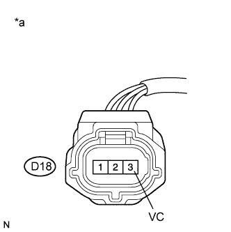
1.INSPECT CAMSHAFT POSITION SENSOR (POWER SOURCE)


    A194108E63
  1. Disconnect the camshaft position sensor connector.

  1. Turn the power switch on (IG).

  1. Measure the voltage according to the value(s) in the table below.

    Standard Voltage:
    Tester Connection
    Switch Condition
    Specified Condition
    D18-3 (VC) - Body ground
    Power switch on (IG)
    4.5 to 5.0 V

    Text in Illustration 
    *a
    Front view of wire harness connector
    (to Camshaft Position Sensor)


NG
Go to step 9
OK


2.CHECK HARNESS AND CONNECTOR (CAMSHAFT POSITION SENSOR - ECM)
  1. Disconnect the camshaft position sensor connector.

  1. Disconnect the ECM connector.

  1. Measure the resistance according to the value(s) in the table below.

    Standard Resistance:

    Tester Connection
    Condition
    Specified Condition
    D18-1 (VVI+) - D27-76 (G2+)
    Always
    Below 1 Ω
    D18-2 (VVI-) - D27-122 (G2-)
    Always
    Below 1 Ω
    D18-1 (VVI+) or D27-76 (G2+) - Body ground
    Always
    10 kΩ or higher
    D18-2 (VVI-) or D27-122 (G2-) - Body ground
    Always
    10 kΩ or higher


NG
REPAIR OR REPLACE HARNESS OR CONNECTOR
OK


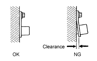
3.CHECK SENSOR INSTALLATION (CAMSHAFT POSITION SENSOR)


    BR03795E17
  1. Check the camshaft position sensor installation.

    OK:
    Sensor is installed correctly.


NG
SECURELY REINSTALL SENSOR (Click here)
OK


4.INSPECT INTAKE CAMSHAFT (TIMING ROTOR)
  1. Check the timing rotor of the intake camshaft.

    OK:
    Timing rotor does not have any cracks or deformation.


NG
REPLACE INTAKE CAMSHAFT (Click here)
OK


5.REPLACE CAMSHAFT POSITION SENSOR
  1. Replace the camshaft position sensor (Click here).


NEXT


6.CHECK WHETHER DTC OUTPUT RECURS (P0340, P0342 OR P0343)
  1. Connect the intelligent tester to the DLC3.

  1. Turn the power switch on (IG).

  1. Turn the tester on.

  1. Clear the DTCs (Click here).

  1. Drive the vehicle in accordance with the driving pattern described in the Confirmation Driving Pattern.

  1. Enter the following menus: Powertrain / Engine and ECT / DTC.

  1. Read the DTCs.
    Result 
    Result
    Proceed to
    DTC P0340, P0342 or P0343 is output
    A
    DTC is not output
    B

    HINT:
    If the engine does not start, replace the ECM.


B
END
A


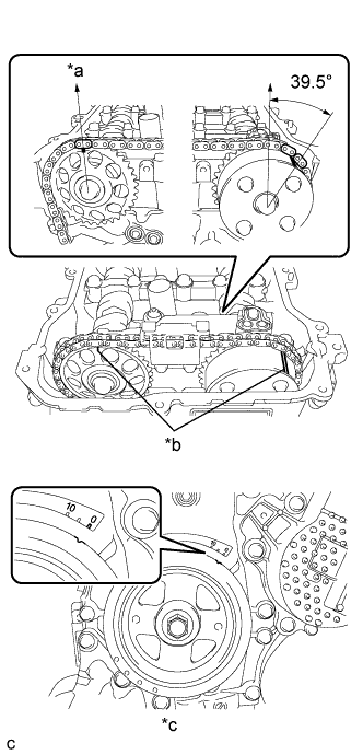
7.ADJUST VALVE TIMING
A216026E02

HINT:
There are no marks on the cylinder head to match-up for the purpose of checking valve timing. Valve timing can only be inspected by lining up the colored plates on the timing chain with the marks on the pulleys. It may be necessary to remove and reinstall the chain to match-up the alignment marks (Click here).

Text in Illustration 
*a
Top
*b
Alignment Mark
*c
No. 1 Cylinder at TDC Compression

NEXT


8.CHECK WHETHER DTC OUTPUT RECURS (P0340, P0342 OR P0343)
  1. Connect the intelligent tester to the DLC3.

  1. Turn the power switch on (IG).

  1. Turn the tester on.

  1. Clear the DTCs (Click here).

  1. Drive the vehicle in accordance with the driving pattern described in the Confirmation Driving Pattern.

  1. Enter the following menus: Powertrain / Engine and ECT / DTC.

  1. Read the DTCs.
    Result 
    Result
    Proceed to
    DTC is not output
    A
    DTC P0340, P0342 or P0343 is output
    B

    HINT:
    If the engine does not start, replace the ECM.


B
REPLACE ECM (Click here)
A

END 

9.CHECK HARNESS AND CONNECTOR (CAMSHAFT POSITION SENSOR - ECM)
  1. Disconnect the camshaft position sensor connector.

  1. Disconnect the ECM connector.

  1. Measure the resistance according to the value(s) in the table below.

    Standard Resistance:

    Tester Connection
    Condition
    Specified Condition
    D18-3 (VC) - D27-99 (VCV1)
    Always
    Below 1 Ω
    D18-3 (VC) or D27-99 (VCV1) - Body ground
    Always
    10 kΩ or higher


NG
REPAIR OR REPLACE HARNESS OR CONNECTOR
OK

REPLACE ECM (Click here)