CAN COMMUNICATION SYSTEM > HOW TO PROCEED WITH TROUBLESHOOTING

for Preparation Click here


NOTICE:
  1. Refer to Diagnosis System for the DTCs for the CAN communication.
  2. Refer to troubleshooting of each system if DTCs regarding the CAN communication system are not output.
  3. After turning the power switch off, waiting time may be required before disconnecting the cable from the negative (-) auxiliary battery terminal. Therefore, make sure to read the disconnecting the cable from the negative (-) auxiliary battery terminal notices before proceeding with work (Click here).

HINT:
*: Use the intelligent tester.


1.VEHICLE BROUGHT TO WORKSHOP

    NEXT


    2.CUSTOMER PROBLEM ANALYSIS
    1. Interview the customer and confirm the problem.


    NEXT


    3.CHECK BATTERY

      Standard Voltage:
      11 to 14 V

      HINT:
      If the voltage is below 11 V, recharge or replace the battery before proceeding to the next step.


    NEXT


    4.CHECK AND CLEAR DTCS*

      HINT:
      1. CAN communication DTCs are stored when there is an open or short in any of the communication wires. Any problems with the power source of a corresponding ECU or sensor, or problems in the ECU or the sensor itself also cause these DTCs to be stored.
      2. If a CAN communication wire connector is disconnected with the power switch on (IG), the ECUs of the corresponding system and related systems store a DTC.


    NEXT


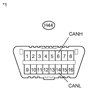
    5.CHECK DLC3 BRANCH LINE AND V1 BUS MAIN LINE (CANH - CANL)

      NOTICE:
      1. Turn the power switch off before measuring the resistances between CAN main bus lines and between CAN bus branch lines.
      2. Turn the power switch off before inspecting CAN bus lines for a ground short.
      3. After the power switch is turned off, check that the key reminder warning system and light reminder warning system are not operating.
      4. Before measuring the resistance, leave the vehicle as is for at least 1 minute and do not operate the power switch, any other switches or the doors. If any doors need to be opened in order to check connectors, open the doors and leave them open.

      HINT:
      1. Operating the power switch, any other switches or a door triggers related ECU and sensor communication on the CAN. This communication will cause the resistance value to change.
      2. Even after DTCs are cleared, if a DTC is stored again after driving the vehicle for a while, the malfunction may be occurring due to vibration of the vehicle. In such a case, wiggling the ECUs or wire harness while performing the inspection below may help determine the cause of the malfunction.


      C210421E28
    1. Turn the power switch off.

    2. Measure the resistance according to the value(s) in the table below.

      Standard Resistance:
      Tester Connection
      Switch Condition
      Specified Condition
      H44-6 (CANH) - H44-14 (CANL)
      Power switch off
      54 to 69 Ω

      Text in Illustration 
      *1
      DLC3

      Result:
      Result
      Proceed to
      OK
      A
      NG (70 Ω or higher)
      B
      NG (Below 54 Ω) for LHD
      C
      NG (Below 54 Ω) for RHD
      D


    B.
    GO TO OPEN IN CAN MAIN BUS LINE (Click here)

    C.
    GO TO SHORT IN CAN BUS LINES (LHD Models) (Click here)

    D.
    GO TO SHORT IN CAN BUS LINES (RHD Models) (Click here)
    A


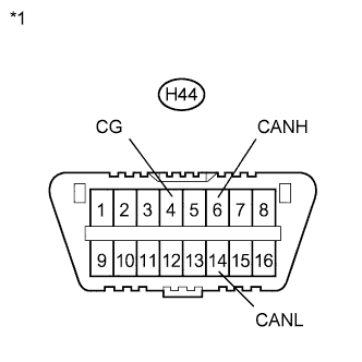
    6.CHECK FOR SHORT TO GND IN V1 BUS (CANH, CANL - CG)


      C210421E29
    1. Turn the power switch off.

    2. Measure the resistance according to the value(s) in the table below.

      Standard Resistance:
      Tester Connection
      Switch Condition
      Specified Condition
      H44-6 (CANH) - H44-4 (CG)
      Power switch off
      200 Ω or higher
      H44-14 (CANL) - H44-4 (CG)
      Power switch off
      200 Ω or higher

      Text in Illustration 
      *1
      DLC3

    3. Result:
      Result
      Proceed to
      OK
      A
      NG (LHD)
      B
      NG (RHD)
      C


    B.
    GO TO SHORT TO GND IN CAN BUS LINE (LHD Models) (Click here)

    C.
    GO TO SHORT TO GND IN CAN BUS LINE (RHD Models) (Click here)
    A


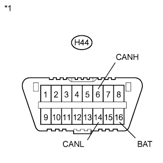
    7.CHECK FOR SHORT TO +B IN V1 BUS (CANH, CANL - BAT)


      C210421E30
    1. Disconnect the cable from the negative (-) auxiliary battery terminal.

    2. Measure the resistance according to the value(s) in the table below.

      Standard Resistance:
      Tester Connection
      Condition
      Specified Condition
      H44-6 (CANH) - H44-16 (BAT)
      Cable disconnected from negative (-) auxiliary battery terminal
      6 kΩ or higher
      H44-14 (CANL) - H44-16 (BAT)
      Cable disconnected from negative (-) auxiliary battery terminal
      6 kΩ or higher

      Text in Illustration 
      *1
      DLC3

    3. Result:
      Result
      Proceed to
      OK
      A
      NG (LHD)
      B
      NG (RHD)
      C


    B.
    GO TO SHORT TO +B IN CAN BUS LINE (LHD Models) (Click here)

    C.
    GO TO SHORT TO +B IN CAN BUS LINE (RHD Models) (Click here)
    A


    8.CHECK INSTALLED SYSTEMS (ECU AND SENSOR) THAT USE CAN COMMUNICATION
    1. Based on the vehicle equipment and specifications, confirm the systems that use CAN communication (Click here).


    NEXT


    9.CHECK ECUS CONNECTED TO CAN BUS*
    1. Select "Communication Bus Check" from the screen on the intelligent tester (Click here).

    2. Observe the screen for approximately 1 minute to check the ECUs and sensors displayed on the screen.

      Result:

      Result
      Proceed to
      All ECUs and sensors connected to the CAN communication system are displayed on the screen.
      (CAN bus circuit is currently normal.)
      A
      1. All ECUs except the power management control ECU connected to the V2 bus are not displayed on the screen.
      2. The power management control ECU (PM1 Gateway) outputs DTC U1002.
      (Open or short in V2 bus main lines.)
      B
      1. All ECUs except the power management control ECU connected to the power management bus are not displayed on the screen.
      2. The power management control ECU (PM2 Gateway) outputs DTC U1002.
      (Open or short in power management bus main lines.)
      C
      1. All ECUs except the main body ECU connected to the CAN MS bus are not displayed on the screen.
      2. The main body ECU outputs DTC U1002.
      (Open or short in CAN MS bus main lines.)
      D
      All ECUs connected to the CAN MS bus are not displayed on the screen.
      (Open in main body ECU branch line or main body ECU malfunction.)
      E
      All ECUs connected to the V2 bus and power management bus are not displayed on the screen.
      (Open in power management control ECU branch lines or power management control ECU malfunction.)
      F
      One of the ECUs and sensors connected to the V1 bus is not displayed on the screen.
      (Open in ECU or sensor branch lines, or communication interrupted.)
      G
      1. One of the ECUs and sensors connected to the V2 bus or power management bus is not displayed on the screen.
        (Open in ECU or sensor branch lines, or communication interrupted.)
      2. One of the ECUs and sensors connected to the CAN MS bus is not displayed on the screen.
        (Open in ECU or sensor branch lines, or communication interrupted.)
      H
      Some ECUs and sensors repeatedly appear and disappear on the screen during this check.
      (Open in one side of ECU or sensor branch lines.)
      I

      NOTICE:
      1. The systems (ECUs and sensors) that adopt CAN communication vary depending on the vehicle and optional equipment. Check which systems (ECUs and sensors) are installed on the vehicle (Click here).
      2. Non-installed ECUs or sensors will not be displayed. Do not mistake them for being in communication stop mode.
      3. The ECUs and sensors that repeatedly appear and disappear from the screen during this check are considered normal. (The response to the intelligent tester and its display are affected by signals output from other ECUs which have an open circuit in either of their CAN bus branch lines.)

      HINT:
      1. The ECUs connected to the V2 bus and power management bus are displayed on the screen by the power management control ECU.
      2. The ECUs connected to the CAN MS bus are displayed on the screen by the main body ECU.


    B.
    GO TO U1002 (POWER MANAGEMENT1) (Click here)

    C.
    GO TO U1002 (POWER MANAGEMENT2) (Click here)

    D.
    GO TO U1002 (MAIN BODY) (Click here)

    E.
    GO TO MAIN BODY ECU COMMUNICATION STOP MODE (Click here)

    F.
    GO TO POWER MANAGEMENT CONTROL ECU COMMUNICATION STOP MODE (Click here)

    G.
    GO TO COMMUNICATION STOP MODE TABLE (Click here)

    H.
    GO TO DIAGNOSTIC TROUBLE CODE CHART (Click here)

    I.
    GO TO OPEN IN ONE SIDE OF CAN BRANCH LINE (Click here)
    A


    10.RECHECK DTC

      HINT:
      1. Sometimes CAN communication system DTCs are output, but all ECUs and sensors connected to the CAN communication system are displayed on the intelligent tester. In this case, previous or history DTCs may indicate the cause of the problem.
      2. ECUs related to a problem in the CAN bus will store DTCs to indicate communication malfunctions. Communication stop mode in the CAN bus can be determined by comparing the combination of DTCs that have been set. Refer to DTC Combination Table for the CAN bus.
      3. The power management control ECU will store communication error DTCs when the ECUs connected to the V2 bus and power management bus cannot communicate, or if a network malfunction occurs.
      4. The main body ECU will store communication error DTCs when the ECUs connected to the CAN MS bus cannot communicate, or if a network malfunction occurs.


      Result:

      Result
      Proceed to
      Communication error DTCs other than the codes output from the power management control ECU are output.
      (A malfunction occurred in the V1 bus.)
      A
      The power management control ECU (PM1 Gateway) outputs DTC U1002.
      (A malfunction occurred in the V2 bus.)
      B
      The power management control ECU (PM2 Gateway) outputs DTC U1002.
      (A malfunction occurred in the power management bus.)
      C
      The main body ECU (Main Body) outputs DTC U1002.
      (A malfunction occurred in the CAN MS bus.)
      D
      The main body ECU outputs DTCs other than DTC U1002.
      (A malfunction occurred in an ECU branch line connected to the CAN MS bus.)
      E
      The power management ECU outputs DTCs other than DTC U1002.
      (A malfunction occurred in an ECU branch line connected to the V2 bus or power management bus.)
      F


    B.
    GO TO U1002 (POWER MANAGEMENT1) (Click here)

    C.
    GO TO U1002 (POWER MANAGEMENT2) (Click here)

    D.
    GO TO U1002 (MAIN BODY) (Click here)

    E.
    GO TO DIAGNOSTIC TROUBLE CODE CHART (Click here)

    F.
    GO TO DIAGNOSTIC TROUBLE CODE CHART (Click here)
    A


    11.DTC COMBINATION TABLE
    1. Confirm the problem according to the combination of output DTCs regarding the CAN communication system (Click here).

      HINT:
      CAN communication system history DTCs may indicate the problem if CAN communication system DTCs are output and all ECUs and sensors connected to the CAN communication system are displayed on "Communication Bus Check" of the intelligent tester.


    NEXT


    12.CIRCUIT INSPECTION

      NEXT


      13.IDENTIFICATION OF PROBLEM

        NEXT


        14.REPAIR OR REPLACEMENT

          NEXT


          15.CONFIRMATION TEST*

            NEXT

            END