POWER SWITCH > INSPECTION |
| 1. INSPECT POWER SWITCH |
Measure the resistance according to the value(s) in the table below.
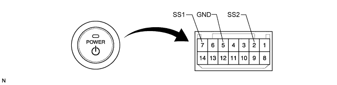
| Tester Connection | Switch Condition | Specified Condition |
| 7 (SS1) - 5 (GND) | Pushed | Below 1 Ω |
| 2 (SS2) - 5 (GND) | Pushed | Below 1 Ω |
| 7 (SS1) - 5 (GND) | Not pushed | 10 kΩ or higher |
| 2 (SS2) - 5 (GND) | Not pushed | 10 kΩ or higher |
Apply battery voltage between the terminals of the switch, and check the illumination condition of the power switch.
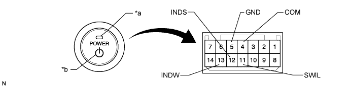
| *1 | Indicator Light | *2 | Power Switch Illumination |
| Measurement Condition | Specified Condition |
| Auxiliary battery positive (+) →Terminal 11 (SWIL) Auxiliary battery negative (-) →Terminal 4 (COM) or 5 (GND) | Illuminates (Power Switch Illumination) |
| Auxiliary battery positive (+) →Terminal 12 (INDS) Auxiliary battery negative (-) →Terminal 4 (COM) or 5 (GND) | Illuminates (Indicator Light) |
| Auxiliary battery positive (+) →Terminal 13 (INDW) Auxiliary battery negative (-) →Terminal 4 (COM) or 5 (GND) | Illuminates (Indicator Light) |
