SFI SYSTEM > MIL Circuit |
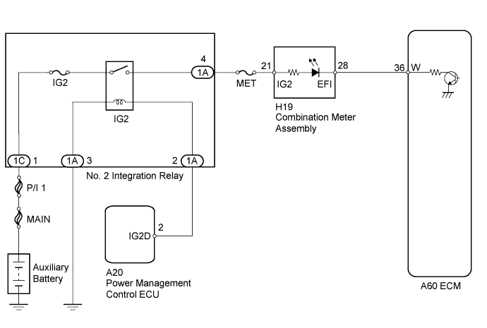
| 1.CHECK THAT MIL IS ILLUMINATED |
Turn the power switch on (IG).
Check the illumination of the MIL.
| Condition | Proceed to |
| MIL remains illuminated (Even after power switch is turned on (IG) and several seconds have passed, MIL still remains illuminated) | A |
| MIL remains off (Does not illuminate at all) | B |
| MIL illuminates for several seconds, but turns off after engine is started | C |
|
| ||||
|
| ||||
| A | |
 |
| 2.CHECK WHETHER MIL TURNS OFF |
Connect the intelligent tester to the DLC3.
Turn the power switch on (IG).
Turn the tester on.
Enter the following menus: Powertrain / Engine and ECT / DTC.
Check if any DTCs have been stored. Note down the DTCs.
Clear the DTCs (Click here).
Check if the MIL goes off.
|
| ||||
| OK | ||
 | ||
| ||
| 3.CHECK HARNESS AND CONNECTOR (CHECK FOR SHORT IN WIRE HARNESS) |
Disconnect the A60 ECM connector.
Turn the power switch on (IG).
Check that the MIL is not illuminated.
|
| ||||
| OK | ||
| ||
| ||
| 4.CHECK HARNESS AND CONNECTOR (COMBINATION METER ASSEMBLY - ECM) |
Disconnect the combination meter assembly connector.
Disconnect the ECM connector.
Measure the resistance according to the value(s) in the table below.
| Tester Connection | Condition | Specified Condition |
| H19-28 (EFI) or A60-36 (W) - Body ground | Always | 10 kΩ or higher |
|
| ||||
| OK | ||
| ||
| ||
| 5.CHECK THAT ENGINE STARTS |
Turn the power switch on (IG).
Put the engine in inspection mode (maintenance mode) (Click here).
Start the engine.
| Result | Proceed to |
| Engine starts | A |
| Engine cannot be put in inspection mode* (Engine cannot start) | B |
|
| ||||
| A | |
|
| 6.CHECK HARNESS AND CONNECTOR (ECM TERMINAL VOLTAGE) |
Disconnect the ECM connector.
Turn the power switch on (IG).
Measure the voltage according to the value(s) in the table below.
| Tester Connection | Switch Condition | Specified Condition |
| A60-36 (W) - Body ground | Power switch on (IG) | 11 to 14 V |
|
| ||||
| OK | ||
| ||
| ||
| 7.CHECK HARNESS AND CONNECTOR (COMBINATION METER ASSEMBLY - ECM) |
Disconnect the combination meter assembly connector.
Disconnect the ECM connector.
Measure the resistance according to the value(s) in the table below.
| Tester Connection | Condition | Specified Condition |
| H19-28 (EFI) - A60-36 (W) | Always | Below 1 Ω |
|
| ||||
| OK | ||
| ||
| ||


