BRAKE SYSTEM > ON-VEHICLE INSPECTION |
| 1. INSPECT PRESSURE SENSOR |
Check auxiliary battery voltage.
Set a pedal effort gauge and SST, and connect the intelligent tester.
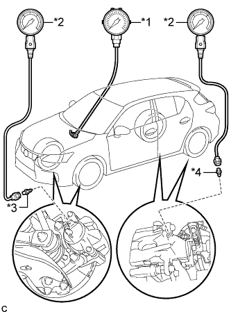 |
Set a pedal effort gauge and SST.
| *1 | Pedal Effort Gauge |
| *2 | SST (LSPV Gauge) |
| *3 | SST (No. 1 Nipple) |
| *4 | SST (No. 3 Nipple) |
Bleed air from SST (LSPV gauge) (Click here).
Connect the intelligent tester to the DLC3 with the power switch off, park (P) selected and the parking brake applied.
Turn the power switch on (IG) and turn the intelligent tester on.
Clear the DTCs (Click here).
Inspect wheel cylinder pressure sensor and regulator pressure sensor.
Enter the following menus: Chassis / ABS/VSC/TRC / Active Test / Power Supply Air Bleeding Pattern 1.
Select "Wheel Cylinder Pressure Sensor" and "Regulator Pressure Sensor Output".
Check the value output from "Wheel Cylinder Pressure Sensor" and "Regulator Pressure Sensor Output" by depressing the brake pedal.
| Pedal Effort N (kgf, lbf) | Regulator Pressure Sensor Output (V) | Rear Right Wheel Hydraulic Pressure (MPa (kgf/cm2, psi)) | Rear Left Wheel Hydraulic Pressure (MPa (kgf/cm2, psi)) |
| 50 (5, 11.2) | 0.57 to 1.37 | 0.3 to 4.3 (3.1 to 43.8, 44 to 623) | 0.3 to 4.3 (3.1 to 43.8, 44 to 623) |
| 100 (10, 22.5) | 1.48 to 2.28 | 4.8 to 8.8 (49.0 to 89.7, 697 to 1276) | 4.8 to 8.8 (49.0 to 89.7, 697 to 1276) |
| 150 (15, 33.7) | 2.4 to 3.2 | 9.3 to 13.3 (94.9 to 135.6, 1349 to 1929) | 9.3 to 13.3 (94.9 to 135.6, 1349 to 1929) |
| 200 (20, 45.0) | 3.3 to 4.1 | 13.8 to 17.8 (140.8 to 181.5, 2002 to 2581) | 13.8 to 17.8 (140.8 to 181.5, 2002 to 2581) |
| Pedal Effort N (kgf, lbf) | Wheel Cylinder Pressure Sensor (V) | Front Right Wheel Hydraulic Pressure (MPa (kgf/cm2, psi)) | Front Left Wheel Hydraulic Pressure (MPa (kgf/cm2, psi)) |
| 50 (5, 11.2) | 0.5 to 1.3 | 0.0 to 3.96 (0.0 to 40.3, 0 to 574) | 0.0 to 3.96 (0.0 to 40.3, 0 to 574) |
| 100 (10, 22.5) | 1.28 to 2.08 | 3.8 to 7.8 (38.8 to 79.5, 552 to 1131) | 3.8 to 7.8 (38.8 to 79.5, 552 to 1131) |
| 150 (15, 33.7) | 2.07 to 2.87 | 7.66 to 11.66 (78.2 to 118.8, 1112 to 1691) | 7.66 to 11.66 (78.2 to 118.8, 1112 to 1691) |
| 200 (20, 45.0) | 2.85 to 3.65 | 12.48 to 15.48 (127.3 to 157.8, 1811 to 2245) | 12.48 to 15.48 (127.3 to 157.8, 1811 to 2245) |
After inspection, turn "Power Supply Air Bleeding Pattern 1" off.
Remove pedal effort gauge and SST.
Remove pedal effort gauge and SST, and bleed brake line (Click here).
Inspect accumulator sensor.
Enter the following menus: Chassis / ABS/VSC/TRC / Data List "Accumulator Sensor".
Depress the brake pedal 4 or 5 times and operate the booster pump motor.
After confirming that the booster pump motor stops, check the output voltage.
| 2. INSPECT BRAKE BOOSTER WITH MASTER CYLINDER ASSEMBLY |
Check auxiliary battery voltage.
Connect the intelligent tester and set a pedal effort gauge.
Set a pedal effort gauge.
Connect the intelligent tester to the DLC3 with the power switch off, park (P) selected and the parking brake applied.
Turn the power switch on (IG) and turn the intelligent tester on.
Clear the DTCs (Click here).
Check operation without the brake booster.
Inspect and adjust the brake pedal height.
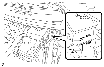 |
Adjust the brake fluid level in the reservoir between the MIN line and fluid level support line.
| *1 | Fluid Level Support Line |
| *2 | MIN Line |
Turn the intelligent tester on and enter the following menus: Chassis / ABS/VSC/TRC / Utility / ECB (Electronically Controlled Brake system) Utility / Zero Down.
Enter the following menus: Chassis / ABS/VSC/TRC / Data List "Wheel Cylinder Pressure Sensor", "Stroke Sensor" and "Stroke Sensor 2".
Check the value output from "Wheel Cylinder Pressure Sensor", "Stroke Sensor" and "Stroke Sensor 2" by depressing the brake pedal.
| Pedal Effort N (kgf, lbf) | Wheel Cylinder Pressure Sensor (V) | Stroke Sensor (V) | Stroke Sensor 2 (V) |
| 200 (20, 45.0) | 0.492 to 1.292 | 0.97 to 1.67 | 3.33 to 4.03 |
| 500 (51, 112.4) | 1.08 to 1.88 | 1.15 to 1.85 | 3.15 to 3.85 |
Turn the power switch off to finish "Zero Down".
Turn the power switch on and wait for 20 seconds, then enter the following menus: Chassis / ABS/VSC/TRC / Data List "Accumulator Sensor", and check the output voltage.
| 3. INSPECT STROKE SIMULATOR |
Check auxiliary battery voltage.
Connect the intelligent tester and set a pedal effort gauge.
Set a pedal effort gauge.
Connect the intelligent tester to the DLC3 with the power switch off, park (P) selected and the parking brake applied.
Turn the power switch on (IG) and turn the intelligent tester on.
Clear the DTCs (Click here).
Check operation with the brake booster.
Turn the power switch on (IG).
Enter the following menus: Chassis / ABS/VSC/TRC / Data List "Stroke Sensor" and "Stroke Sensor 2".
Depress the brake pedal 4 or 5 times.
Check the value output from "Stroke Sensor" and "Stroke Sensor 2" by depressing the brake pedal.
| Pedal Effort N (kgf, lbf) | Stroke Sensor (V) | Stroke Sensor 2 (V) |
| 50 (5, 11.2) | 1.04 to 1.74 | 3.26 to 3.96 |
| 100 (10, 22.5) | 1.21 to 1.91 | 3.09 to 3.79 |
| 150 (15, 33.7) | 1.30 to 2.00 | 3.00 to 3.70 |
