FRONT DOOR > ADJUSTMENT |
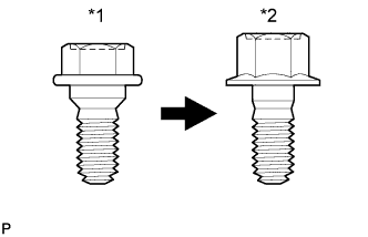
| *1 | Centering Bolt |
| *2 | Standard Bolt |
| 1. INSPECT FRONT DOOR |
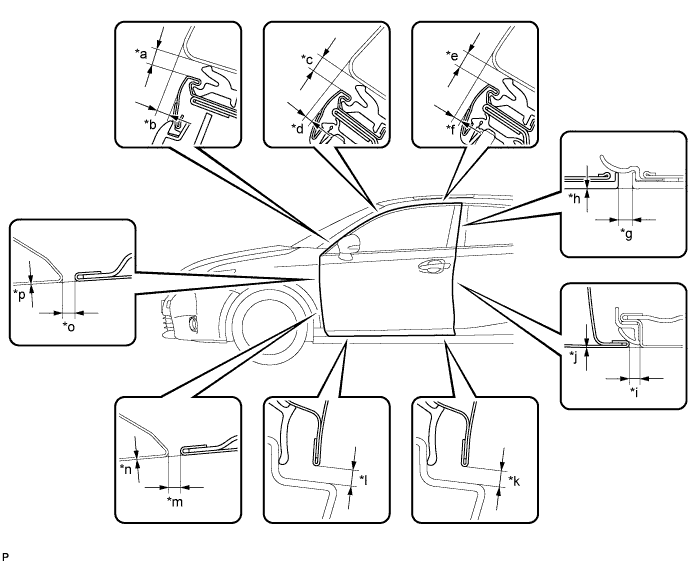
Check that the clearance measurements of areas *a through *p are within each standard range.
| Area | Measurement | Area | Measurement |
| *a | 3.35 to 6.35 mm (0.132 to 0.250 in.) | *b | 2.5 to 5.5 mm (0.0984 to 0.217 in.) |
| *c | 3.35 to 6.35 mm (0.132 to 0.250 in.) | *d | 1.0 to 4.0 mm (0.0394 to 0.157 in.) |
| *e | 3.35 to 6.35 mm (0.132 to 0.250 in.) | *f | 1.0 to 4.0 mm (0.0394 to 0.157 in.) |
| *g | 3.0 to 6.0 mm (0.118 to 0.236 in.) | *h | -1.5 to 1.5 mm (-0.0591 to 0.0591 in.) |
| *i | 2.7 to 5.7 mm (0.106 to 0.224 in.) | *j | -1.5 to 1.5 mm (-0.0591 to 0.0591 in.) |
| *k | 3.65 to 6.65 mm (0.144 to 0.262 in.) | *l | 3.65 to 6.65 mm (0.144 to 0.262 in.) |
| *m | 2.5 to 5.5 mm (0.0984 to 0.217 in.) | *n | -1.5 to 1.5 mm (-0.0591 to 0.0591 in.) |
| *o | 2.5 to 5.5 mm (0.0984 to 0.217 in.) | *p | -1.5 to 1.5 mm (-0.0591 to 0.0591 in.) |
| 2. ADJUST FRONT DOOR |
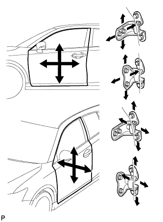 |
Using SST, loosen the hinge bolts on the vehicle body and adjust the door position.
Tighten the hinge bolts on the vehicle body after the adjustment.
Loosen the hinge bolts on the door and adjust the door position.
Tighten the hinge bolts on the door after the adjustment.
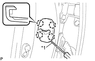 |
Using a screwdriver, disengage the 4 claws and remove door lock striker cover.
| *1 | Protective Tape |
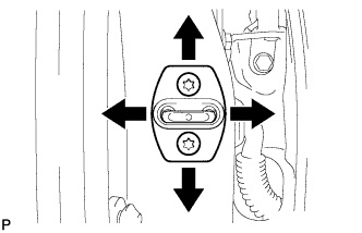 |
Using a T40 "TORX" socket wrench, slightly loosen the striker mounting screws.
Using a brass bar and a hammer, hit the striker to adjust its position.
Using a T40 "TORX" socket wrench, tighten the striker mounting screws after adjustment.
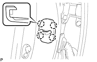 |
Engage the 4 claws and install the door lock striker cover.
