DTC B2271 Ignition Hold Monitor Malfunction |
| DTC Code | DTC Detection Condition | Trouble Area | DTC Output Confirmation Operation |
| B2271 | Either condition is met (1-trip detection logic*):
|
| Turn the power switch on (IG).
|
| Vehicle Condition when Malfunction Detected | Fail-safe Function when Malfunction Detected |
| The power source mode is not allowed to change to on (IG) (the hybrid control system cannot be started). | The power source mode cannot be changed to on (IG). |
| DTC | Data List Item | Active Test Item |
| B2271 | Power Source Control
| - |
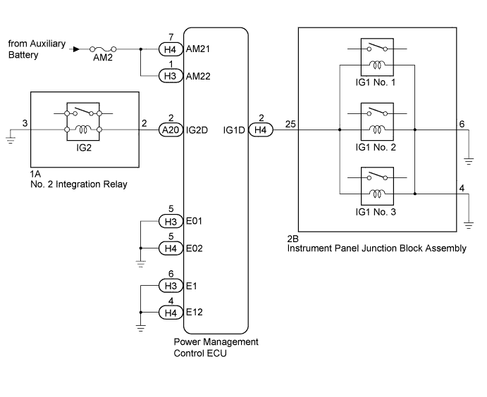
| 1.CHECK HARNESS AND CONNECTOR (AUXILIARY BATTERY - POWER MANAGEMENT CONTROL ECU) |
Disconnect the H3 and H4 connectors from the power management control ECU.
Measure the voltage according to the value(s) in the table below.
| Tester Connection | Condition | Specified Condition |
| H3-1 (AM22) - Body ground | Always | 9.5 to 16 V |
| H4-7 (AM21) - Body ground | Always | 9.5 to 16 V |
|
| ||||
| OK | |
 |
| 2.CHECK HARNESS AND CONNECTOR (POWER MANAGEMENT CONTROL ECU - BODY GROUND) |
Measure the resistance according to the value(s) in the table below.
| Tester Connection | Condition | Specified Condition |
| H3-5 (E01) - Body ground | Always | Below 1 Ω |
| H3-6 (E1) - Body ground | Always | Below 1 Ω |
| H4-4 (E12) - Body ground | Always | Below 1 Ω |
| H4-5 (E02) - Body ground | Always | Below 1 Ω |
|
| ||||
| OK | |
|
| 3.INSPECT NO. 2 INTEGRATION RELAY (IG2 RELAY) |
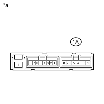 |
Remove the No.2 integration relay. (Click here)
Measure the resistance according to the value(s) in the table below.
| Tester Connection | Condition | Specified Condition |
| 1A-2 - 1A-3 | 20°C (68°F) | 130 to 230 Ω |
| *a | Component without harness connected (No.2 Integration Relay) |
|
| ||||
| OK | |
|
| 4.INSPECT INSTRUMENT PANEL JUNCTION BLOCK ASSEMBLY (IG1 NO. 1, IG1 NO. 2 AND IG1 NO. 3 RELAYS) |
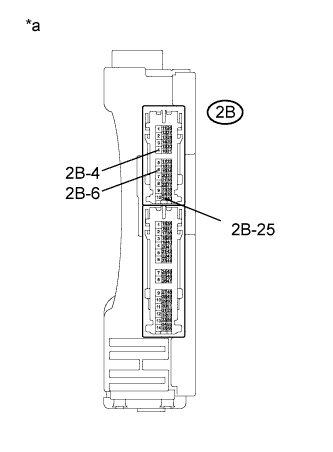 |
Remove the instrument panel junction block assembly (Click here).
Measure the resistance according to the value(s) in the table below.
| Tester Connection | Condition | Specified Condition |
| 2B-25 - 2B-4 | 20°C (68°F) | 52.32 to 79.32 Ω |
| 2B-25 - 2B-6 | 20°C (68°F) | 52.32 to 79.32 Ω |
| 2B-4 - 2B-6 | Always | Below 1 Ω |
| *a | Component without harness connected (Instrument Panel Junction Block Assembly) |
|
| ||||
| OK | |
|
| 5.CHECK HARNESS AND CONNECTOR (POWER MANAGEMENT CONTROL ECU - INSTRUMENT PANEL JUNCTION BLOCK) |
Measure the resistance according to the value(s) in the table below.
| Tester Connection | Condition | Specified Condition |
| H4-2 (IG1D) - 2B-25 | Always | Below 1 Ω |
| H4-2 (IG1D) - Body ground | Always | 10 kΩ or higher |
|
| ||||
| OK | |
|
| 6.CHECK HARNESS AND CONNECTOR (INSTRUMENT PANEL JUNCTION BLOCK ASSEMBLY - BODY GROUND) |
Measure the resistance according to the value(s) in the table below.
| Tester Connection | Condition | Specified Condition |
| 2B-4 - Body ground | Always | Below 1 Ω |
| 2B-6 - Body ground | Always | Below 1 Ω |
|
| ||||
| OK | |
|
| 7.CHECK HARNESS AND CONNECTOR (POWER MANAGEMENT CONTROL ECU - NO. 2 INTEGRATION RELAY) |
Measure the resistance according to the value(s) in the table below.
| Tester Connection | Condition | Specified Condition |
| A20-2 (IG2D) - 1A-2 | Always | Below 1 Ω |
| A20-2 (IG2D) - Body ground | Always | 10 kΩ or higher |
|
| ||||
| OK | |
|
| 8.CHECK HARNESS AND CONNECTOR (NO. 2 INTEGRATION RELAY - BODY GROUND) |
Measure the resistance according to the value(s) in the table below.
| Tester Connection | Condition | Specified Condition |
| 1A-3 - Body ground | Always | Below 1 Ω |
|
| ||||
| OK | |
|
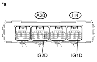
| 9.CHECK POWER MANAGEMENT CONTROL ECU |
 |
Install the instrument panel junction block assembly (Click here).
Install the No. 2 integration relay.
Reconnect the A20 and H4 connectors.
Measure the voltage according to the value(s) in the table below.
| Tester Connection | Condition | Specified Condition |
| A20-2 (IG2D) - Body ground | Power switch on (IG) | Output voltage at terminal AM21 or AM22 is -2.5 V or more |
| H4-2 (IG1D) - Body ground | Power switch on (IG) | Output voltage at terminal AM21 or AM22 is -2.5 V or more |
| *a | Component with harness connected (Power Management Control ECU) |
|
| ||||
| OK | ||
 | ||
| ||

