DTC B2282 Vehicle Speed Signal Malfunction |
| DTC Code | DTC Detection Condition | Trouble Area | DTC Output Confirmation Operation |
| B2282 | Mismatch between the vehicle speed signal from the direct line sent by the combination meter and the vehicle speed signal sent via CAN communication (1-trip detection logic*). |
| Drive the vehicle for 20 seconds at a vehicle speed of 25 km/h (16 mph) or more, and then drive the vehicle at a vehicle speed that is less than 5 km/h (3 mph) for 20 seconds. |
| DTC Code | Vehicle Condition when Malfunction Detected | Fail-safe Function when Malfunction Detected |
| B2282 |
| - |
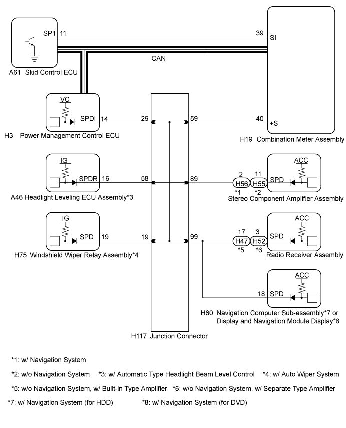
| DTC | Data List Item | Active Test Item |
| B2282 | Power Source Control
Combination Meter
| - |
| 1.CHECK CAN COMMUNICATION SYSTEM |
Check if CAN communication DTCs are output.
|
| ||||
| OK | |
 |
| 2.CHECK SPEEDOMETER OPERATION |
Connect the intelligent tester to the DLC3.
Turn the power switch on (IG).
Turn the intelligent tester on.
Enter the following menus: Body / Combination Meter / Data List.
Check the Data List for proper functioning of the vehicle speed signal.
| Tester Display | Measurement Item/Range | Normal Condition | Diagnostic Note |
| Vehicle Speed Meter | Vehicle speed/Min.: 0, Max.: 255 | Almost same as actual speed (When driving) | - |
|
| ||||
| OK | |
|
| 3.READ VALUE USING INTELLIGENT TESTER |
Enter the following menus: Body / Power Source Control / Data List.
Read the Data List according to the display on the intelligent tester.
| Tester Display | Measurement Item/Range | Normal Condition | Diagnostic Note |
| Vehicle speed signal | Vehicle speed signal/Stop or Run | Stop: Vehicle stopped Run: Vehicle running | - |
|
| ||||
| OK | ||
 | ||
| ||
| 4.CHECK HARNESS AND CONNECTOR (AUXILIARY BATTERY - POWER MANAGEMENT CONTROL ECU) |
Disconnect the H3 and H4 connectors from the power management control ECU.
Measure the voltage according to the value(s) in the table below.
| Tester Connection | Condition | Specified Condition |
| H3-1 (AM22) - Body ground | Always | 9.5 to 16 V |
| H4-7 (AM21) - Body ground | Always | 9.5 to 16 V |
|
| ||||
| OK | |
|
| 5.CHECK HARNESS AND CONNECTOR (POWER MANAGEMENT CONTROL ECU - BODY GROUND) |
Measure the resistance according to the value(s) in the table below.
| Tester Connection | Condition | Specified Condition |
| H3-5 (E01) - Body ground | Always | Below 1 Ω |
| H3-6 (E1) - Body ground | Always | Below 1 Ω |
| H4-4 (E12) - Body ground | Always | Below 1 Ω |
| H4-5 (E02) - Body ground | Always | Below 1 Ω |
|
| ||||
| OK | |
|
| 6.CHECK HARNESS AND CONNECTOR (COMBINATION METER ASSEMBLY - POWER MANAGEMENT CONTROL ECU) |
Disconnect the H19 connector from the combination meter assembly.
Measure the resistance according to the value(s) in the table below.
| Tester Connection | Condition | Specified Condition |
| H3-14 (SPDI) - H19-40 (+S) | Always | Below 1 Ω |
| H3-14 (SPDI) - Body ground | Always | 10 kΩ or higher |
|
| ||||
| OK | |
|
| 7.INSPECT COMBINATION METER ASSEMBLY |
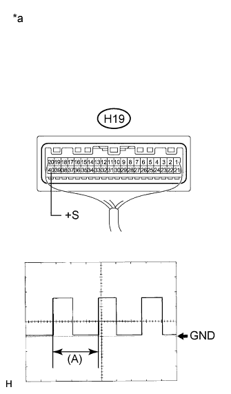 |
Remove the combination meter assembly (Click here).
Reconnect the H19 connector to the combination meter assembly.
Reconnect the H3 connector to the power management control ECU.
Connect an oscilloscope to terminal H19-40 (+S) and body ground.
Turn the power switch on (IG).
Turn a wheel slowly.
Check the signal waveform according to the condition(s) in the table below.
| Item | Condition |
| Tool setting | 5 V/DIV., 20 ms/DIV. |
| Vehicle condition | Wheel being turned |
| *a | Component with harness connected (Combination Meter Assembly) |
|
| ||||
| OK | ||
| ||
| ||
| 8.CHECK HARNESS AND CONNECTOR (COMBINATION METER ASSEMBLY - JUNCTION CONNECTOR) |
Disconnect the H117 connector.
Measure the resistance according to the value(s) in the table below.
| Tester Connection | Condition | Specified Condition |
| H19-40 (+S) - H117-59 | Always | Below 1 Ω |
| H19-40 (+S) - Body ground | Always | 10 kΩ or higher |
|
| ||||
| OK | |
|
| 9.CHECK HARNESS AND CONNECTOR (POWER MANAGEMENT CONTROL ECU - JUNCTION CONNECTOR) |
Measure the resistance according to the value(s) in the table below.
| Tester Connection | Condition | Specified Condition |
| H3-14 (SPDI) - H117-29 | Always | Below 1 Ω |
| H3-14 (SPDI) - Body ground | Always | 10 kΩ or higher |
|
| ||||
| OK | ||
| ||
| ||


