DTC B1805/52 Short in Front Passenger Side Squib Circuit |
DTC B1806/52 Open in Front Passenger Side Squib Circuit |
DTC B1807/52 Short to GND in Front Passenger Side Squib Circuit |
DTC B1808/52 Short to B+ in Front Passenger Side Squib Circuit |
| DTC No. | DTC Detection Condition | Trouble Area |
| B1805/52 |
|
|
| B1806/52 |
| |
| B1807/52 |
| |
| B1808/52 |
|
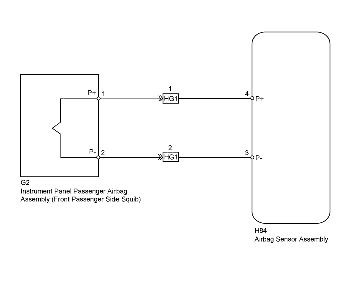
| 1.CHECK CONNECTORS |
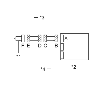 |
Turn the power switch off.
Disconnect the cable from the negative (-) auxiliary battery terminal.
Check that the connectors are properly connected to the instrument panel passenger airbag assembly and airbag sensor assembly. Also check that the connectors that link the instrument panel wire and No. 3 instrument panel wire are properly connected.
Disconnect the connectors from the instrument panel passenger airbag assembly and airbag sensor assembly. Also disconnect the instrument panel wire from the No. 3 instrument panel wire.
Check that the terminals of the connectors are not damaged.
Check that the No. 3 instrument panel wire connector (on the instrument panel passenger airbag assembly side) is not damaged.
Check that the short springs for the instrument panel wire and No. 3 instrument panel wire with the activation prevention mechanism are not deformed or damaged.
| *1 | Instrument Panel Passenger Airbag Assembly |
| *2 | Airbag Sensor Assembly |
| *3 | No. 3 Instrument Panel Wire |
| *4 | Instrument Panel Wire |
|
| ||||
| OK | |
 |
| 2.CHECK INSTRUMENT PANEL PASSENGER AIRBAG ASSEMBLY (FRONT PASSENGER SIDE SQUIB) |
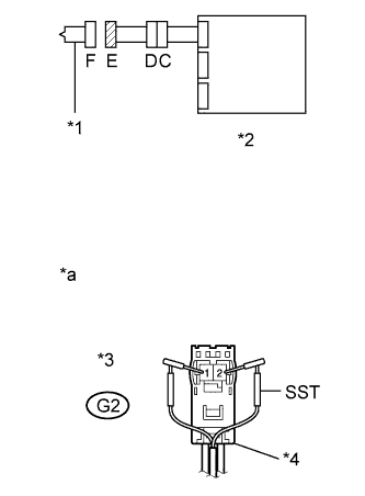 |
Connect the instrument panel wire to the No. 3 instrument panel wire and airbag sensor assembly.
Connect SST (resistance 2.1 Ω) to connector E (orange connector).
Connect the cable to the negative (-) auxiliary battery terminal.
Turn the power switch on (IG), and wait for at least 60 seconds.
Clear the DTCs stored in memory (Click here).
Turn the power switch off.
Turn the power switch on (IG), and wait for at least 60 seconds.
Check for DTCs (Click here).
| *1 | Instrument Panel Passenger Airbag Assembly |
| *2 | Airbag Sensor Assembly |
| *3 | Connector E |
| *4 | Color: Orange |
| *a | Front view of wire harness connector (to Instrument Panel Passenger Airbag Assembly) |
|
| ||||
| OK | ||
 | ||
| ||
| 3.CHECK FRONT PASSENGER SIDE SQUIB CIRCUIT |
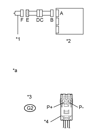 |
Turn the power switch off.
Disconnect the cable from the negative (-) auxiliary battery terminal.
Disconnect SST from connector E.
Disconnect the instrument panel wire from the airbag sensor assembly.
Check for a short to B+ in the circuit.
Connect the cable to the negative (-) auxiliary battery terminal.
Turn the power switch on (IG).
Measure the voltage according to the value(s) in the table below.
| Tester Connection | Switch Condition | Specified Condition |
| G2-1 (P+) - Body ground | Power switch on (IG) | Below 1 V |
| G2-2 (P-) - Body ground | Power switch on (IG) | Below 1 V |
Check for an open in the circuit.
Turn the power switch off.
Disconnect the cable from the negative (-) auxiliary battery terminal.
Measure the resistance according to the value(s) in the table below.
| Tester Connection | Condition | Specified Condition |
| G2-1 (P+) - G2-2 (P-) | Always | Below 1 Ω |
Check for a short to ground in the circuit.
Measure the resistance according to the value(s) in the table below.
| Tester Connection | Condition | Specified Condition |
| G2-1 (P+) - Body ground | Always | 1 MΩ or higher |
| G2-2 (P-) - Body ground | Always | 1 MΩ or higher |
Check for a short in the circuit.
Release the activation prevention mechanism built into connector B (Click here).
Measure the resistance according to the value(s) in the table below.
| Tester Connection | Condition | Specified Condition |
| G2-1 (P+) - G2-2 (P-) | Always | 1 MΩ or higher |
| *1 | Instrument Panel Passenger Airbag Assembly |
| *2 | Airbag Sensor Assembly |
| *3 | Connector E |
| *4 | Color: Orange |
| *a | Front view of wire harness connector (to Instrument Panel Passenger Airbag Assembly) |
|
| ||||
| OK | |
|
| 4.CHECK AIRBAG SENSOR ASSEMBLY |
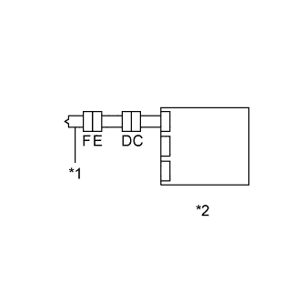 |
Restore the released activation prevention mechanism of connector B to the original condition.
Connect the connectors to the instrument panel passenger airbag assembly and airbag sensor assembly.
Connect the cable to the negative (-) auxiliary battery terminal.
Turn the power switch on (IG), and wait for at least 60 seconds.
Clear the DTCs stored in memory (Click here).
Turn the power switch off.
Turn the power switch on (IG), and wait for at least 60 seconds.
Check for DTCs (Click here).
| *1 | Instrument Panel Passenger Airbag Assembly |
| *2 | Airbag Sensor Assembly |
|
| ||||
| OK | ||
| ||
| ||
| 5.CHECK INSTRUMENT PANEL WIRE |
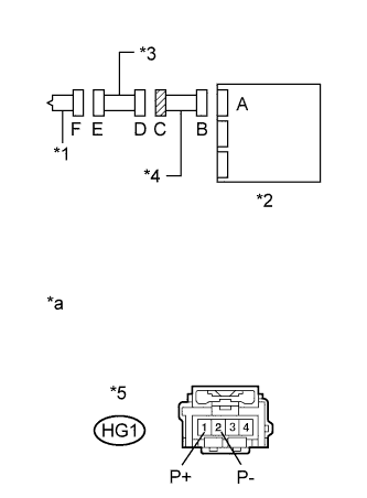 |
Restore the released activation prevention mechanism of connector B to the original condition.
Disconnect the No. 3 instrument panel wire from the instrument panel wire.
Check for a short to B+ in the circuit.
Connect the cable to the negative (-) auxiliary battery terminal.
Turn the power switch on (IG).
Measure the voltage according to the value(s) in the table below.
| Tester Connection | Switch Condition | Specified Condition |
| HG1-1 (P+) - Body ground | Power switch on (IG) | Below 1 V |
| HG1-2 (P-) - Body ground | Power switch on (IG) | Below 1 V |
Check for an open in the circuit.
Turn the power switch off.
Disconnect the cable from the negative (-) auxiliary battery terminal.
Measure the resistance according to the value(s) in the table below.
| Tester Connection | Condition | Specified Condition |
| HG1-1 (P+) - HG1-2 (P-) | Always | Below 1 Ω |
Check for a short to ground in the circuit.
Measure the resistance according to the value(s) in the table below.
| Tester Connection | Condition | Specified Condition |
| HG1-1 (P+) - Body ground | Always | 1 MΩ or higher |
| HG1-2 (P-) - Body ground | Always | 1 MΩ or higher |
Check for a short in the circuit.
Release the activation prevention mechanism built into connector B (Click here).
Measure the resistance according to the value(s) in the table below.
| Tester Connection | Condition | Specified Condition |
| HG1-1 (P+) - HG1-2 (P-) | Always | 1 MΩ or higher |
| *1 | Instrument Panel Passenger Airbag Assembly |
| *2 | Airbag Sensor Assembly |
| *3 | No. 3 Instrument Panel Wire |
| *4 | Instrument Panel Wire |
| *5 | Connector C |
| *a | Front view of wire harness connector (to No. 3 Instrument Panel Wire) |
|
| ||||
| OK | |
|
| 6.CHECK NO. 3 INSTRUMENT PANEL WIRE |
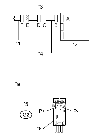 |
Check for a short to B+ in the circuit.
Connect the cable to the negative (-) auxiliary battery terminal.
Turn the power switch on (IG).
Measure the voltage according to the value(s) in the table below.
| Tester Connection | Switch Condition | Specified Condition |
| G2-1 (P+) - Body ground | Power switch on (IG) | Below 1 V |
| G2-2 (P-) - Body ground | Power switch on (IG) | Below 1 V |
Check for an open in the circuit.
Turn the power switch off.
Disconnect the cable from the negative (-) auxiliary battery terminal.
Measure the resistance according to the value(s) in the table below.
| Tester Connection | Condition | Specified Condition |
| G2-1 (P+) - G2-2 (P-) | Always | Below 1 Ω |
Check for a short to ground in the circuit.
Measure the resistance according to the value(s) in the table below.
| Tester Connection | Condition | Specified Condition |
| G2-1 (P+) - Body ground | Always | 1 MΩ or higher |
| G2-2 (P-) - Body ground | Always | 1 MΩ or higher |
Check for a short in the circuit.
Release the activation prevention mechanism built into connector D (Click here).
Measure the resistance according to the value(s) in the table below.
| Tester Connection | Condition | Specified Condition |
| G2-1 (P+) - G2-2 (P-) | Always | 1 MΩ or higher |
| *1 | Instrument Panel Passenger Airbag Assembly |
| *2 | Airbag Sensor Assembly |
| *3 | No. 3 Instrument Panel Wire |
| *4 | Instrument Panel Wire |
| *5 | Connector E |
| *6 | Color: Orange |
| *a | Front view of wire harness connector (to Instrument Panel Passenger Airbag Assembly) |
|
| ||||
| OK | ||
| ||
| ||


