ELECTRONICALLY CONTROLLED BRAKE SYSTEM > TERMINALS OF ECU

for Preparation Click here


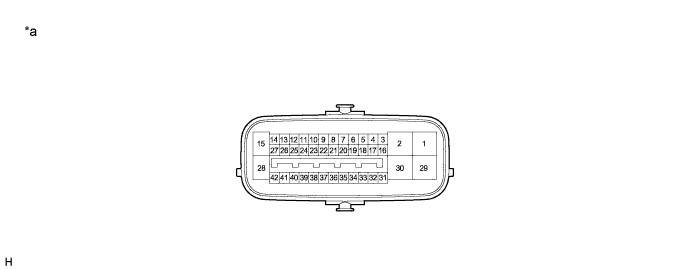
TERMINALS OF ECU
*1: w/ Dynamic Radar Cruise Control System
*2: w/ Emergency Brake Signal

C156569E02


Text in Illustration 
*a
Component without harness connected
(Skid Control ECU)
-
-

Terminal No. (Symbol)
Terminal Description
1 (MRI1)
Motor power supply input 1
2 (MRI2)
Motor power supply input 2
3 (STP0)
Stop light control relay output
4 (TS)
Sensor check switch input
5 (FR-)
Front speed sensor RH (-) signal input
6 (STP2)
Stop light control relay input
7 (RL-)
Rear speed sensor LH (-) signal input
8
- (Not used)
9 (RR-)
Rear speed sensor RH (-) signal input
10 (HZRI)
Hazard warning switch input
11 (SP1)
Speed sensor signal output
12 (IG2)
IG2 power source input
13 (BZ)*1
Skid control buzzer output
14 (BI)
+B power source input
15 (BS)
Solenoid power supply input
16 (IG1)
IG1 power source input
17
- (Not used)
18 (FR+)
Front speed sensor RH (+) power supply output
19 (CTY)
Courtesy switch input
20 (RL+)
Rear speed sensor LH (+) power supply output
21 (EXO)*2
Stop light control relay output
22 (RR+)
Rear speed sensor RH (+) power supply output
23 (GND6)
Skid control ECU ground 6
24 (GND5)
Skid control ECU ground 5
25 (GND4)
Skid control ECU ground 4
26 (GND3)
Skid control ECU ground 3
27 (GND2)
Skid control ECU ground 2
28 (GND)
Skid control ECU ground
29 (MRO1)
Motor power supply output 1
30 (MRO2)
Motor power supply output 2
31 (FL+)
Front speed sensor LH (+) power supply output
32 (FL-)
Front speed sensor LH (-) signal input
33 (STP)
Stop light switch input
34 (CA2L)
CAN communication line 2 (L)
35 (CA2H)
CAN communication line 2 (H)
36 (LBL)
Brake fluid level warning switch input
37 (CA1H)
CAN communication line 1 (H)
38 (CA1L)
CAN communication line 1 (L)
39 (VCSK)
Stroke sensor power supply output
40 (SKS2)
Stroke sensor signal input 2
41 (SKG)
Stroke sensor ground
42 (SKS)
Stroke sensor signal input

TERMINAL INSPECTION


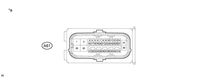
  1. Disconnect the connector and measure the voltage or resistance on the wire harness side.


    C156570E04


    Text in Illustration 
    *a
    Front view of wire harness connector
    (to Skid Control ECU)
    -
    -

    HINT:
    Voltage cannot be measured with the connector connected to the skid control ECU as the connector is watertight.


    Standard 
    Terminal No. (Symbol)
    Wiring Color
    Terminal Description
    Condition
    Specified Condition
    A61-1 (MRI1) - Body ground
    B - Body ground
    Motor power supply input 1
    Always
    11 to 14 V
    A61-2 (MRI2) - Body ground
    R - Body ground
    Motor power supply input 2
    Always
    11 to 14 V
    A61-3 (STP0) - Body ground
    Y - Body ground
    Stop light control relay output
    Always
    11 to 14 V
    A61-6 (STP2) - Body ground
    BE - Body ground
    Stop light control relay input
    Stop light switch ON → OFF
    (Brake pedal depressed → released)
    11 to 14 V → Below 1.5 V
    A61-10 (HZRI) - Body ground
    SB - Body ground
    Hazard warning switch input
    Hazard warning switch ON → OFF
    Below 1 Ω → 10 kΩ or higher
    A61-12 (IG2) - Body ground
    BE - Body ground
    IG2 power source input
    Power switch on (IG)
    11 to 14 V
    A61-13 (BZ) - Body ground*1
    BR - Body ground
    Skid control buzzer output
    Power switch on (IG), buzzer not sounding
    11 to 14 V
    A61-14 (BI) - Body ground
    W - Body ground
    +B power source input
    Always
    11 to 14 V
    A61-15 (BS) - Body ground
    B - Body ground
    Solenoid power supply input
    Always
    11 to 14 V
    A61-16 (IG1) - Body ground
    B - Body ground
    IG1 power source input
    Power switch on (IG)
    11 to 14 V
    A61-19 (CTY) - Body ground
    V - Body ground
    Courtesy switch input
    Driver door close → open
    11 to 14 V → Below 1.5 V
    A61-21 (EXO) - Body ground*2
    BE - Body ground
    Stop light control relay output
    Stop light switch ON → OFF
    (Brake pedal depressed → released)
    11 to 14 V → Below 1.5 V
    A61-23 (GND6) - Body ground
    W-B - Body ground
    Skid control ECU ground 6
    Always
    Below 1 Ω
    A61-24 (GND5) - Body ground
    W-B - Body ground
    Skid control ECU ground 5
    Always
    Below 1 Ω
    A61-25 (GND4) - Body ground
    W-B - Body ground
    Skid control ECU ground 4
    Always
    Below 1 Ω
    A61-26 (GND3) - Body ground
    W-B - Body ground
    Skid control ECU ground 3
    Always
    Below 1 Ω
    A61-27 (GND2) - Body ground
    W-B - Body ground
    Skid control ECU ground 2
    Always
    Below 1 Ω
    A61-28 (GND) - Body ground
    W - Body ground
    Skid control ECU ground
    Always
    Below 1 Ω
    A61-33 (STP) - Body ground
    L - Body ground
    Stop light switch input
    Stop light switch ON → OFF
    (Brake pedal depressed → released)
    11 to 14 V → Below 1.5 V
    A61-36 (LBL) - Body ground
    P - Body ground
    Brake fluid level warning switch input
    Brake fluid level warning switch OFF → ON
    1.84 to 2.16 kΩ → Below 1 Ω
    *1: w/ Dynamic Radar Cruise Control System
    *2: w/ Emergency Brake Signal