DTC P0300 Random / Multiple Cylinder Misfire Detected |
DTC P0301 Cylinder 1 Misfire Detected |
DTC P0302 Cylinder 2 Misfire Detected |
DTC P0303 Cylinder 3 Misfire Detected |
DTC P0304 Cylinder 4 Misfire Detected |
| DTC No. | DTC Detection Condition | Trouble Area |
| P0300 | Simultaneous misfiring of several cylinders occurs and one of the following conditions below is detected (2 trip detection logic):
|
|
| P0301 P0302 P0303 P0304 | Misfiring of a specific cylinder occurs and one of the following conditions below is detected (2 trip detection logic):
|
| Required Sensors/Components (Main) | Crankshaft position sensor Camshaft position sensor |
| Required Sensors/Components (Related) | Engine coolant temperature sensor Intake air temperature sensor Mass air flow meter sub-assembly |
| Frequency of Operation | Continuous |
| Either of the following conditions (a) or (b) is met | - |
| (a) Engine coolant temperature at engine start | Higher than -7°C (19°F) |
| (b) Engine coolant temperature | Higher than 20°C (68°F) |
| Duration | Crankshaft 1000 revolutions x 4 |
| Duration | Crankshaft 200 revolutions x 3 |
| Engine Speed | Duration |
| Idling | 4 minutes or more |
| 1000 | 4 minutes and 30 seconds or more |
| 2000 | 2 minutes and 30 seconds or more |
| 3000 | 1 minute and 30 seconds or more |
| 1.CHECK ANY OTHER DTCS OUTPUT (IN ADDITION TO MISFIRE DTCS) |
Connect the intelligent tester to the DLC3.
Turn the power switch on (IG).
Turn the tester on.
Enter the following menus: Powertrain / Engine and ECT / DTC.
Read the DTCs.
| Result | Proceed to |
| DTC P0300, P0301, P0302, P0303 and/or P0304 are output | A |
| DTC P0300, P0301, P0302, P0303 and/or P0304 and other DTCs are output | B |
|
| ||||
| A | |
 |
| 2.CHECK PCV HOSE CONNECTIONS |
Check the PCV hose connections (Click here).
|
| ||||
| OK | |
|
| 3.READ VALUE USING INTELLIGENT TESTER (MISFIRE RPM AND MISFIRE LOAD) |
Connect the intelligent tester to the DLC3.
Turn the power switch on (IG).
Turn the tester on.
Enter the following menus: Powertrain / Engine and ECT / Data List / All Data / Misfire RPM and Misfire Load.
Read and note the Misfire RPM and Misfire Load values.
| NEXT | |
|
| 4.READ VALUE USING INTELLIGENT TESTER (CYLINDER #1 (TO #4) MISFIRE COUNT) |
Connect the intelligent tester to the DLC3.
Turn the power switch on (IG).
Turn the tester on.
Clear the DTCs (Click here).
Put the engine in inspection mode (maintenance mode) (Click here).
Enter the following menus: Powertrain / Engine and ECT / Data List / All Data / Cylinder #1 (to #4) Misfire Count.
Start the engine and allow the engine to idle.
Read each value for Cylinder #1 Misfire Count to Cylinder #4 Misfire Count displayed on the tester. If no misfire counts occur in any cylinders, perform steps (i) and (j) and then check the misfire counts again.
Drive the vehicle with the Misfire RPM and Misfire Load noted in the "Read Value Using Intelligent Tester (Misfire Rpm And Misfire Load)" procedures above.
Read the Cylinder #1 Misfire Count to Cylinder #4 Misfire Count or DTCs displayed on the tester.
| Result | Proceed to |
| Most misfires occur in only 1 or 2 cylinders | A |
| 3 cylinders or more have equal misfire counts | B |
|
| ||||
| A | |
|
| 5.INSPECT SPARK PLUG |
Inspect the spark plug of the misfiring cylinder (Click here).
|
| ||||
| OK | |
|
| 6.CHECK FOR SPARKS AND IGNITION |
Perform a spark test (Click here).
|
| ||||
| OK | |
|
| 7.CHECK CYLINDER COMPRESSION PRESSURE OF MISFIRING CYLINDER |
Measure the cylinder compression pressure of the misfiring cylinder (Click here).
|
| ||||
| OK | |
|
| 8.CHECK FUEL INJECTOR ASSEMBLY (POWER SOURCE VOLTAGE) |
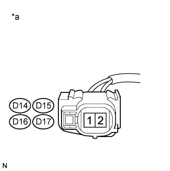 |
Disconnect the fuel injector assembly connectors.
Turn the power switch on (IG).
Measure the voltage according to the value(s) in the table below.
| Tester Connection | Switch Condition | Specified Condition |
| D14-1 - Body ground | Power switch on (IG) | 11 to 14 V |
| D15-1 - Body ground | Power switch on (IG) | 11 to 14 V |
| D16-1 - Body ground | Power switch on (IG) | 11 to 14 V |
| D17-1 - Body ground | Power switch on (IG) | 11 to 14 V |
| *a | Front view of wire harness connector (to Fuel Injector Assembly) |
|
| ||||
| OK | |
|
| 9.CHECK HARNESS AND CONNECTOR (FUEL INJECTOR ASSEMBLY - ECM) |
Disconnect the fuel injector assembly connectors.
Disconnect the ECM connector.
Measure the resistance according to the value(s) in the table below.
| Tester Connection | Condition | Specified Condition |
| D14-2 - D27-85 (#10) | Always | Below 1 Ω |
| D15-2 - D27-84 (#20) | Always | Below 1 Ω |
| D16-2 - D27-83 (#30) | Always | Below 1 Ω |
| D17-2 - D27-82 (#40) | Always | Below 1 Ω |
| D14-2 or D27-85 (#10) - Body ground | Always | 10 Ω or higher |
| D15-2 or D27-84 (#20) - Body ground | Always | 10 Ω or higher |
| D16-2 or D27-83 (#30) - Body ground | Always | 10 Ω or higher |
| D17-2 or D27-82 (#40) - Body ground | Always | 10 Ω or higher |
|
| ||||
| OK | |
|
| 10.CHECK FUEL INJECTOR ASSEMBLY OF MISFIRING CYLINDER |
Check the fuel injector assembly injection (whether fuel volume is high or low, and whether injection pattern is poor) (Click here).
|
| ||||
| OK | |
|
| 11.CHECK INTAKE SYSTEM |
Check the intake system for vacuum leaks (Click here).
|
| ||||
| OK | |
|
| 12.CHECK FUEL PRESSURE |
Check the fuel pressure (Click here).
|
| ||||
| OK | |
|
| 13.READ VALUE USING INTELLIGENT TESTER (COOLANT TEMP) |
Connect the intelligent tester to the DLC3.
Turn the power switch on (IG).
Turn the tester on.
Enter the following menus: Powertrain / Engine and ECT / Data List / Coolant Temp.
Read the Data List twice, when the engine is both cold and warmed up.
| Tester Display | Condition | Specified Condition |
| Coolant Temp | Cold engine | Same as ambient air temperature |
| Warm engine | Between 75 and 100°C (167 and 212°F) |
|
| ||||
| OK | |
|
| 14.READ VALUE USING INTELLIGENT TESTER (MAF) |
Connect the intelligent tester to the DLC3.
Turn the power switch on (IG).
Turn the tester on.
Put the engine in inspection mode (maintenance mode) (Click here).
Start the engine.
Enter the following menus: Powertrain / Engine and ECT / Data List / All Data / MAF and Coolant Temp.
Allow the engine to idle until Coolant Temp reaches 75°C (167°F) or higher.
Read MAF with the engine speed at 2500 rpm.
| Tester Display | Condition | Specified Condition |
| MAF | Shift lever position: P Engine Speed: 2500 rpm | Between 4.5 gm/sec. and 8.5 gm/sec. |
|
| ||||
| OK | |
|
| 15.ADJUST VALVE TIMING |
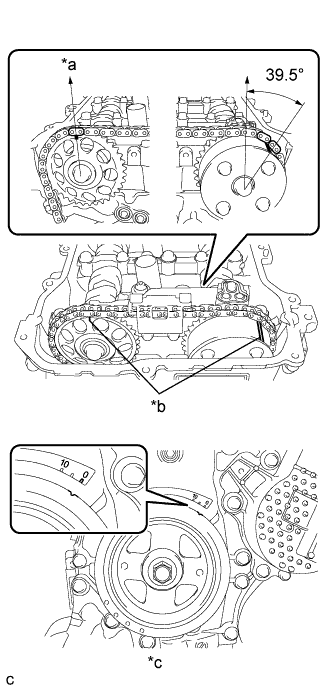 |
| *a | Top |
| *b | Alignment Mark |
| *c | No. 1 Cylinder at TDC Compression |
| NEXT | |
|
| 16.CHECK WHETHER DTC OUTPUT RECURS (P0300, P0301, P0302, P0303 OR P0304) |
Connect the intelligent tester to the DLC3.
Turn the power switch on (IG).
Turn the tester on.
Clear the DTCs (Click here).
Turn the power switch off and wait for at least 30 seconds.
Drive the vehicle in accordance with the driving pattern described in Confirmation Driving Pattern.
Enter the following menus: Powertrain / Engine and ECT / Utility / All Readiness.
Input the DTC: P0300, P0301, P0302, P0303 or P0304.
Check the DTC judgment result.
| Result | Proceed to |
| ABNORMAL (DTC P0300, P0301, P0302, P0303 or P0304 is output) | A |
| NORMAL (DTC is not output) | B |
|
| ||||
| A | |
|
| 17.PERFORM ACTIVE TEST USING INTELLIGENT TESTER (CONTROL THE EGR STEP POSITION) |
Connect the intelligent tester to the DLC3.
Turn the power switch on (IG).
Turn the tester on.
Put the engine in inspection mode (maintenance mode) (Click here).
Start the engine and warm it up until the engine coolant temperature reaches 75°C (167°F) or more.
Enter the following menus: Powertrain / Engine and ECT / Active Test / Control the EGR Step Position / Data List / All Data / Throttle Idle Position and MAP.
Confirm that the Throttle Idle Position is ON and check the engine idling condition and MAP values in the Data List while performing the Active Test.
| - | EGR Step Position (Active Test) | |
| 0 Steps | 0 to 30 Steps | |
| Idling condition | Steady idling | Idling changes from steady to rough idling or stalls |
| MAP (Data List) | MAP value is 20 to 40 kPa (150 to 300 mmHg) (EGR valve is fully closed) | MAP value is at least +10 kPa (75 mmHg) higher than when EGR valve is fully closed |
| Result | Proceed to |
| Outside of standard range | A |
| Within standard range | B |
|
| ||||
| A | |
|
| 18.INSPECT EGR VALVE ASSEMBLY |
Remove the EGR valve assembly (Click here).
Check if the EGR valve is stuck open.
| Result | Proceed to |
| NG | A |
| OK | B |
|
| ||||
| A | ||
 | ||
| ||
| 19.CHECK INTAKE SYSTEM |
Check the intake system for vacuum leaks (Click here).
|
| ||||
| OK | |
|
| 20.CHECK FUEL PRESSURE |
Check the fuel pressure (Click here).
|
| ||||
| OK | |
|
| 21.READ VALUE USING INTELLIGENT TESTER (COOLANT TEMP) |
Connect the intelligent tester to the DLC3.
Turn the power switch on (IG).
Turn the tester on.
Enter the following menus: Powertrain / Engine and ECT / Data List / Coolant Temp.
Read the Data List twice, when the engine is both cold and warmed up.
| Tester Display | Condition | Specified Condition |
| Coolant Temp | Cold engine | Same as ambient air temperature |
| Warm engine | Between 75 and 100°C (167 and 212°F) |
|
| ||||
| OK | |
|
| 22.READ VALUE USING INTELLIGENT TESTER (MAF) |
Connect the intelligent tester to the DLC3.
Turn the power switch on (IG).
Turn the tester on.
Put the engine in inspection mode (maintenance mode) (Click here).
Start the engine.
Enter the following menus: Powertrain / Engine and ECT / Data List / All Data / MAF and Coolant Temp.
Allow the engine to idle until Coolant Temp reaches 75°C (167°F) or higher.
Read MAF with the engine speed at 2500 rpm.
| Tester Display | Condition | Specified Condition |
| MAF | Shift lever position: P Engine Speed: 2500 rpm | Between 4.5 gm/sec. and 8.5 gm/sec. |
|
| ||||
| OK | |
|
| 23.PERFORM ACTIVE TEST USING INTELLIGENT TESTER (CONTROL THE EGR STEP POSITION) |
Connect the intelligent tester to the DLC3.
Turn the power switch on (IG).
Turn the tester on.
Put the engine in inspection mode (maintenance mode) (Click here).
Start the engine and warm it up until the engine coolant temperature reaches 75°C (167°F) or higher.
Enter the following menus: Powertrain / Engine and ECT / Active Test / Control the EGR Step Position / Data List / All Data / Throttle Idle Position and MAP.
Confirm that the Throttle Idle Position is ON and check the engine idling condition and MAP values in the Data List while performing the Active Test.
| - | EGR Step Position (Active Test) | |
| 0 Steps | 0 to 30 Steps | |
| Idling condition | Steady idling | Idling changes from steady to rough idling or stalls |
| MAP (Data List) | MAP value is 20 to 40 kPa (150 to 300 mmHg) (EGR valve is fully closed) | MAP value is at least +10 kPa (75 mmHg) higher than when EGR valve is fully closed |
| Result | Proceed to |
| Outside of standard range | A |
| Within standard range | B |
|
| ||||
| A | |
|
| 24.INSPECT EGR VALVE ASSEMBLY |
Remove the EGR valve assembly (Click here).
Check if the EGR valve is stuck open.
|
| ||||
| OK | |
|
| 25.INSPECT SPARK PLUG |
Inspect the spark plug of the misfiring cylinder (Click here).
|
| ||||
| OK | |
|
| 26.CHECK FOR SPARKS AND IGNITION |
Perform a spark test (Click here).
|
| ||||
| OK | |
|
| 27.CHECK CYLINDER COMPRESSION PRESSURE OF MISFIRING CYLINDER |
Measure the cylinder compression pressure of the misfiring cylinder (Click here).
|
| ||||
| OK | |
|
| 28.CHECK FUEL INJECTOR ASSEMBLY (POWER SOURCE VOLTAGE) |
|
Disconnect the fuel injector assembly connectors.
Turn the power switch on (IG).
Measure the voltage according to the value(s) in the table below.
| Tester Connection | Switch Condition | Specified Condition |
| D14-1 - Body ground | Power switch on (IG) | 11 to 14 V |
| D15-1 - Body ground | Power switch on (IG) | 11 to 14 V |
| D16-1 - Body ground | Power switch on (IG) | 11 to 14 V |
| D17-1 - Body ground | Power switch on (IG) | 11 to 14 V |
| *a | Front view of wire harness connector (to Fuel Injector Assembly) |
|
| ||||
| OK | |
|
| 29.CHECK HARNESS AND CONNECTOR (FUEL INJECTOR ASSEMBLY - ECM) |
Disconnect the fuel injector assembly connectors.
Disconnect the ECM connector.
Measure the resistance according to the value(s) in the table below.
| Tester Connection | Condition | Specified Condition |
| D14-2 - D27-85 (#10) | Always | Below 1 Ω |
| D15-2 - D27-84 (#20) | Always | Below 1 Ω |
| D16-2 - D27-83 (#30) | Always | Below 1 Ω |
| D17-2 - D27-82 (#40) | Always | Below 1 Ω |
| D14-2 or D27-85 (#10) - Body ground | Always | 10 Ω or higher |
| D15-2 or D27-84 (#20) - Body ground | Always | 10 Ω or higher |
| D16-2 or D27-83 (#30) - Body ground | Always | 10 Ω or higher |
| D17-2 or D27-82 (#40) - Body ground | Always | 10 Ω or higher |
|
| ||||
| OK | |
|
| 30.CHECK FUEL INJECTOR ASSEMBLY OF MISFIRING CYLINDER |
Check the fuel injector assembly injection (whether fuel volume is high or low, and whether injection pattern is poor) (Click here).
|
| ||||
| OK | |
|
| 31.ADJUST VALVE TIMING |
|
| *a | Top |
| *b | Alignment Mark |
| *c | No. 1 Cylinder at TDC Compression |
| NEXT | |
|
| 32.CHECK WHETHER DTC OUTPUT RECURS (DTC P0300, P0301, P0302, P0303 OR P0304) |
Connect the intelligent tester to the DLC3.
Turn the power switch on (IG).
Turn the tester on.
Clear the DTCs (Click here).
Turn the power switch off and wait for at least 30 seconds.
Drive the vehicle in accordance with the driving pattern described in the Confirmation Driving Pattern.
Enter the following menus: Powertrain / Engine and ECT / Utility / All Readiness.
Input the DTC: P0300, P0301, P0302, P0303 or P0304.
Check the DTC judgment result.
| Result | Proceed to |
| ABNORMAL (DTC P0300, P0301, P0302, P0303 or P0304 is output) | A |
| NORMAL (DTC is not output) | B |
|
| ||||
| A | |
|
| 33.CHECK HARNESS AND CONNECTOR |
Check the connection and terminal contact pressure of the connectors and wire harness between the mass air flow meter sub-assembly and ECM (Click here).
| NEXT | |
|
| 34.CHECK DTC OUTPUT RECURS (DTC P0300, P0301, P0302, P0303 OR P0304) |
Connect the intelligent tester to the DLC3.
Turn the power switch on (IG).
Turn the tester on.
Clear the DTCs (Click here).
Turn the power switch off and wait for at least 30 seconds.
Drive the vehicle in accordance with the driving pattern described in Confirmation Driving Pattern.
Enter the following menus: Powertrain / Engine and ECT / Utility / All Readiness.
Input the DTC: P0300, P0301, P0302, P0303 or P0304.
Check the DTC judgment result.
| Result | Proceed to |
| ABNORMAL (DTC P0300, P0301, P0302, P0303 or P0304 is output) | A |
| NORMAL (DTC is not output) | B |
|
| ||||
| A | |
|
| 35.CHECK HARNESS AND CONNECTOR (MASS AIR FLOW METER SUB-ASSEMBLY - ECM) |
Disconnect the mass air flow meter sub-assembly connector.
Disconnect the ECM connector.
Measure the resistance according to the value(s) in the table below.
| Tester Connection | Condition | Specified Condition |
| D5-5 (VG) - D27-94 (VG) | Always | Below 1 Ω |
| D5-4 (E2G) - D27-117 (E2G) | Always | Below 1 Ω |
| D5-5 (VG) or D27-94 (VG) - Body ground | Always | 10 kΩ or higher |
|
| ||||
| OK | |
|
| 36.REPLACE MASS AIR FLOW METER SUB-ASSEMBLY |
Replace the mass air flow meter sub-assembly (Click here).
| NEXT | |
|
| 37.CONFIRM WHETHER MALFUNCTION HAS BEEN SUCCESSFULLY REPAIRED |
Connect the intelligent tester to the DLC3.
Turn the power switch on (IG).
Turn the tester on.
Clear the DTCs (Click here).
Turn the power switch off and wait for at least 30 seconds.
Drive the vehicle in accordance with the driving pattern described in the Confirmation Driving Pattern.
Enter the following menus: Powertrain / Engine and ECT / Utility / All Readiness.
Input the DTC: P0300, P0301, P0302, P0303 or P0304.
Check the DTC judgment result.
| Result | Proceed to |
| ABNORMAL (DTC P0300, P0301, P0302, P0303 or P0304 is output) | A |
| NORMAL (DTC is not output) | B |
|
| ||||
| A | ||
| ||
| ||
| 38.CHANGE TO KNOWN GOOD SPARK PLUG AND CHECK SPARK OF MISFIRING CYLINDER |
Change the installed spark plug to a spark plug that functions normally.
Perform a spark test (Click here).
|
| ||||
| OK | ||
| ||
| ||
| 39.CHANGE TO KNOWN GOOD IGNITION COIL ASSEMBLY AND CHECK SPARK OF MISFIRING CYLINDER |
Change the ignition coil assembly to an ignition coil assembly that functions normally.
Perform a spark test (Click here).
|
| ||||
| OK | ||
| ||
| ||
| 40.CHECK FUEL LINE |
Check the fuel lines for leaks or blockage.
|
| ||||
| OK | ||
| ||
| ||


