DTC P0351 Ignition Coil "A" Primary / Secondary Circuit |
DTC P0352 Ignition Coil "B" Primary / Secondary Circuit |
DTC P0353 Ignition Coil "C" Primary / Secondary Circuit |
DTC P0354 Ignition Coil "D" Primary / Secondary Circuit |
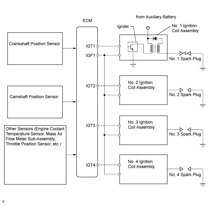
| DTC No. | DTC Detection Conditions | Trouble Areas |
| P0351 P0352 P0353 P0354 | No IGF signal to ECM while engine running (1 trip detection logic). |
|
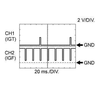 |
| Tester Connection | Tool Setting | Condition | Specified Condition |
| D27-108 (IGT1) - D27-104 (E1) | 2 V/DIV., 20 ms./DIV. | Idling | The correct waveform is as shown |
| D27-107 (IGT2) - D27-104 (E1) | 2 V/DIV., 20 ms./DIV. | Idling | The correct waveform is as shown |
| D27-106 (IGT3) - D27-104 (E1) | 2 V/DIV., 20 ms./DIV. | Idling | The correct waveform is as shown |
| D27-105 (IGT4) - D27-104 (E1) | 2 V/DIV., 20 ms./DIV. | Idling | The correct waveform is as shown |
| D27-23 (IGF1) - D27-104 (E1) | 2 V/DIV., 20 ms./DIV. | Idling | The correct waveform is as shown |
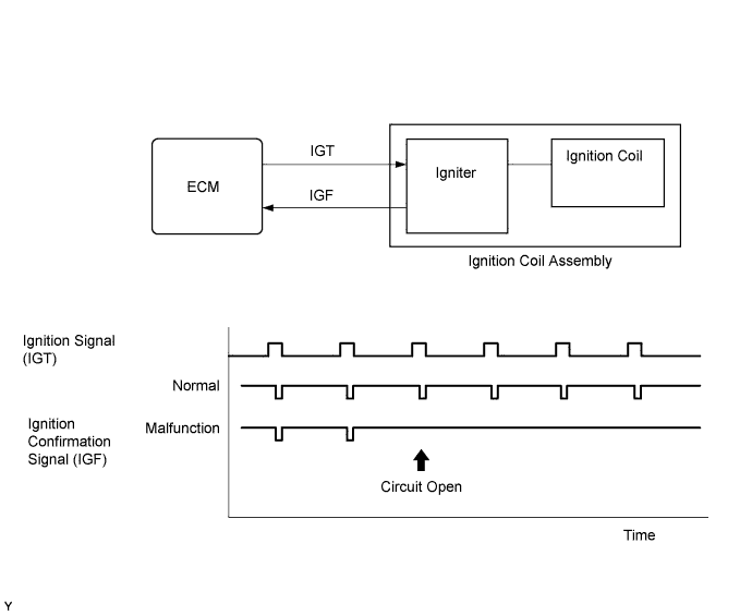
| Required Sensors/Components (Main) | Igniter |
| Required Sensors/Components (Related) | Crankshaft position sensor |
| Frequency of Operation | Continuous |
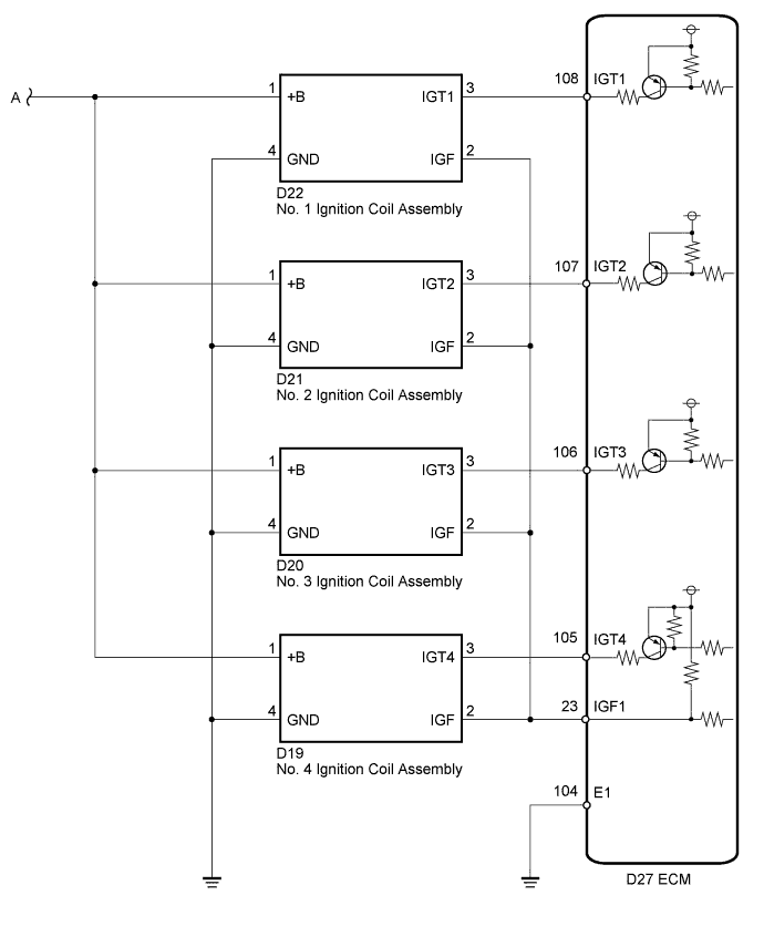
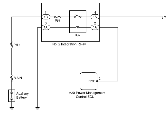
| 1.CHECK HARNESS AND CONNECTOR (IGNITION COIL ASSEMBLY - BODY GROUND) |
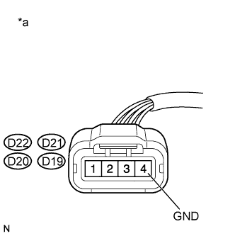 |
Disconnect the ignition coil assembly connectors.
Measure the resistance according to the value(s) in the table below.
| Tester Connection | Condition | Specified Condition |
| D22-4 (GND) - Body ground | Always | Below 1 Ω |
| D21-4 (GND) - Body ground | Always | Below 1 Ω |
| D20-4 (GND) - Body ground | Always | Below 1 Ω |
| D19-4 (GND) - Body ground | Always | Below 1 Ω |
| *a | Front view of wire harness connector (to Ignition Coil Assembly) |
|
| ||||
| OK | |
 |
| 2.INSPECT IGNITION COIL ASSEMBLY (POWER SOURCE) |
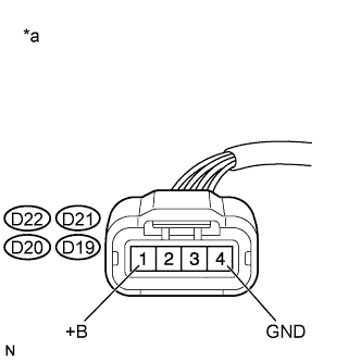 |
Disconnect the ignition coil assembly connectors.
Turn the power switch on (IG).
Measure the voltage according to the value(s) in the table below.
| Tester Connection | Switch Condition | Specified Condition |
| D22-1 (+B) - D22-4 (GND) | Power switch on (IG) | 11 to 14 V |
| D21-1 (+B) - D21-4 (GND) | Power switch on (IG) | 11 to 14 V |
| D20-1 (+B) - D20-4 (GND) | Power switch on (IG) | 11 to 14 V |
| D19-1 (+B) - D19-4 (GND) | Power switch on (IG) | 11 to 14 V |
| *a | Front view of wire harness connector (to Ignition Coil Assembly) |
|
| ||||
| OK | |
|
| 3.CHECK HARNESS AND CONNECTOR (IGNITION COIL ASSEMBLY - ECM) |
Disconnect the ignition coil assembly connectors.
Disconnect the ECM connector.
Measure the resistance according to the value(s) in the table below.
| Tester Connection | Condition | Specified Condition |
| D22-2 (IGF) - D27-23 (IGF1) | Always | Below 1 Ω |
| D21-2 (IGF) - D27-23 (IGF1) | Always | Below 1 Ω |
| D20-2 (IGF) - D27-23 (IGF1) | Always | Below 1 Ω |
| D19-2 (IGF) - D27-23 (IGF1) | Always | Below 1 Ω |
| D22-3 (IGT1) - D27-108 (IGT1) | Always | Below 1 Ω |
| D21-3 (IGT2) - D27-107 (IGT2) | Always | Below 1 Ω |
| D20-3 (IGT3) - D27-106 (IGT3) | Always | Below 1 Ω |
| D19-3 (IGT4) - D27-105 (IGT4) | Always | Below 1 Ω |
| D22-2 (IGF) or D27-23 (IGF1) - Body ground | Always | 10 kΩ or higher |
| D21-2 (IGF) or D27-23 (IGF1) - Body ground | Always | 10 kΩ or higher |
| D20-2 (IGF) or D27-23 (IGF1) - Body ground | Always | 10 kΩ or higher |
| D19-2 (IGF) or D27-23 (IGF1) - Body ground | Always | 10 kΩ or higher |
| D22-3 (IGT1) or D27-108 (IGT1) - Body ground | Always | 10 kΩ or higher |
| D21-3 (IGT2) or D27-107 (IGT2) - Body ground | Always | 10 kΩ or higher |
| D20-3 (IGT3) or D27-106 (IGT3) - Body ground | Always | 10 kΩ or higher |
| D19-3 (IGT4) or D27-105 (IGT4) - Body ground | Always | 10 kΩ or higher |
|
| ||||
| OK | |
|
| 4.CHECK WHETHER DTC OUTPUT RECURS (DTC P0351, P0352, P0353 OR P0354) |
Connect the intelligent tester to the DLC3.
Turn the power switch on (IG).
Turn the tester on.
Clear the DTCs (Click here).
Shuffle arrangement of the ignition coil assemblies (among No. 1 to No. 4 cylinders).
Drive the vehicle in accordance with the driving pattern described in the Confirmation Driving Pattern.
Enter the following menus: Powertrain / Engine and ECT / DTC.
Read the DTCs.
| Result | Proceed to |
| Same DTC output | A |
| Different ignition coil DTC output | B |
|
| ||||
| A | ||
 | ||
| ||

