DTC P3004-803 Power Cable Malfunction |
| DTC No. | INF Code | DTC Detection Condition | Trouble Area |
| P3004 | 803 | While the power switch is on (READY), the electric battery fuse in the service plug grip is burned out, the service plug grip is removed, or SMRB or SMRG is open. |
|
| 1.CHECK DTC OUTPUT (HYBRID CONTROL) |
Connect the intelligent tester to the DLC3.
Turn the power switch on (IG).
Enter the following menus: Powertrain / Hybrid Control / DTC.
Check if DTCs are output.
| Result | Proceed to |
| P3004-803 only is output. | A |
| Any of the following DTCs are also output. | B |
| P0A95-123 is also output. | C |
| DTC No. | Relevant Diagnosis |
| P0A1A-151, 155, 156, 658, 659 | Generator Control Module |
| P0A1B-164, 193, 512, 661, 786 | Drive Motor "A" Control Module |
| P0A1D-148 | Hybrid Powertrain Control Module |
| P0A78-266, 267, 586 | Drive Motor "A" Inverter Performance |
| P0A94-442 | DC/DC Converter Performance |
| P0ADB-227 | Hybrid Battery Positive Contactor Control Circuit Low |
| P0ADC-226 | Hybrid Battery Positive Contactor Control Circuit High |
| P0ADF-229 | Hybrid Battery Negative Contactor Control Circuit Low |
| P0AE0-228 | Hybrid Battery Negative Contactor Control Circuit High |
| P0C76-523 | Hybrid Battery System Discharge Time Too Long |
| P2511-149 | ECM/PCM Power Relay Sensor Circuit Intermittent |
| P3004-131, 132 | Power Cable Malfunction |
| P324E-788 | MG-ECU Power Relay Intermittent Circuit |
| U0110 (all INF codes)*1 | Lost Communication with Drive Motor Control Module |
Turn the power switch off.
|
| ||||
|
| ||||
| A | |
 |
| 2.CLEAR DTC |
Connect the intelligent tester to the DLC3.
Turn the power switch on (IG).
Enter the following menus: Powertrain / Hybrid Control / DTC.
Read and record the DTCs and freeze frame data.
Clear DTCs and freeze frame data.
Turn the power switch off.
| NEXT | |
|
| 3.CHECK DTC OUTPUT (HYBRID CONTROL) |
Connect the intelligent tester to the DLC3.
Turn the power switch on (READY).
Ensure the safety of the areas in front and at the back of the vehicle.
Move the shift lever to D and depress both the accelerator pedal and brake pedal at the same time.
Enter the following menus: Powertrain / Hybrid Control / DTC.
Check if DTCs are output.
| Result | Proceed to |
| P3004-803 is output, or no DTCs are output. | A |
| Power switch is not turned on (READY) and P3004- 131 is output. | B |
Turn the power switch off.
|
| ||||
| A | |
|
| 4.CHECK CONNECTOR CONNECTION CONDITION (POWER MANAGEMENT CONTROL ECU CONNECTOR) |
Check the connections of the power management control ECU connectors.
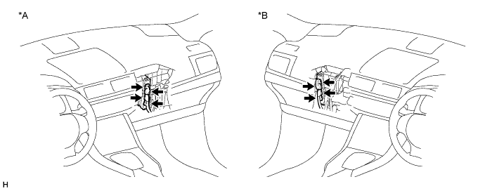
| *A | for LHD | *B | for RHD |
|
| ||||
| OK | |
|
| 5.CHECK HARNESS AND CONNECTOR (POWER MANAGEMENT CONTROL ECU - HYBRID BATTERY JUNCTION BLOCK) |
Check that the service plug grip is not installed.
Disconnect connector H3 from the power management control ECU.
Remove the upper hybrid battery cover sub-assembly (Click here).
Disconnect connector i3 from the hybrid battery junction block assembly.
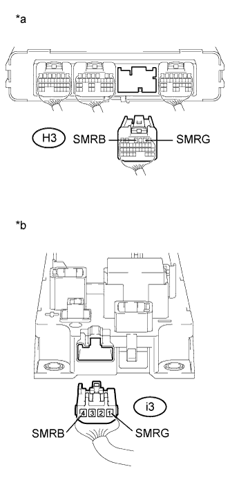 |
Measure the resistance according to the value(s) in the table below.
| Tester Connection | Switch Condition | Specified Condition |
| H3-4 (SMRB) - i3-4 (SMRB) | Power switch off | Below 1 Ω |
| H3-2 (SMRG) - i3-1 (SMRG) | Power switch off | Below 1 Ω |
| *a | Rear view of wire harness connector (to Power Management Control ECU) |
| *b | Rear view of wire harness connector (to Hybrid Battery Junction Block Assembly) |
Connect hybrid battery junction block assembly connector.
Install the upper hybrid battery cover sub-assembly (Click here).
Connect the power management control ECU connector.
|
| ||||
| OK | ||
 | ||
| ||

