PUSH-BUTTON START SYSTEM > TERMINALS OF ECU |
| CHECK POWER MANAGEMENT CONTROL ECU |
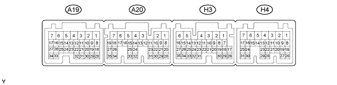
Disconnect the A20, H3 and H4 connectors.
Measure the voltage and resistance according to the value(s) in the table below.
| Tester Connection | Input/Output | Wiring Color | Terminal Description | Condition | Specified Condition | Related Data List Item |
| A20-2 (IG2D) - Body ground | Output | V - Body ground | IG2 signal | 20°C (68°F) | 131 to 230 Ω | IG2 Relay Monitor (Outside) |
| A20-23 (STP) - Body ground | Input | L - Body ground | Stop light switch signal | Brake pedal depressed → Brake pedal released | 9 V or higher → 1 V or less | Stop Light Switch1 |
| H3-1 (AM22) - Body ground | Input | W - Body ground | +B power supply | Always | 9.5 to 14 V | - |
| H4-7 (AM21) - Body ground | Input | W - Body ground | +B power supply | Always | 9.5 to 14 V | - |
| H3-6 (E1) - Body ground | - | W-B - Body ground | Ground | Always | Below 1 Ω | - |
| H4-4 (E12) - Body ground | - | W-B - Body ground | Ground | Always | Below 1 Ω | - |
| H4-24 (CA1L) - Body ground | Input/Output | V - Body ground | CAN communication line | Always | 10 kΩ or higher | - |
| H4-25 (CA1H) - Body ground | Input/Output | P - Body ground | CAN communication line | Always | 10 kΩ or higher | - |
| H4-17 (SSW2) - Body ground | Input | Y - Body ground | SSW2 contact signal (backup for SSW1 and has same behavior as SSW1) | Power switch pushed → power switch not pushed | Below 1 Ω → 10 kΩ or higher | Start Switch2 |
| H3-7 (SSW1) - Body ground | Input | B - Body ground | SSW1 contact signal | Power switch pushed → power switch not pushed | Below 1 Ω → 10 kΩ or higher | Start Switch1 |
| H4-1 (ACCD) - Body ground | Output | G - Body ground | ACC signal | 20°C (68°F) | 81.49 to 118.98 Ω | ACC Relay Monitor |
| H4-2 (IG1D) - Body ground | Output | B - Body ground | IG1 signal | 20°C (68°F) | 54.32 to 79.32 Ω | IG1 Relay Monitor (Outside) |
| H4-11 (LIN2) - Body ground | Input/Output | B - Body ground | LIN communication line | Always | 10 kΩ or higher | - |
Reconnect the A20, H3 and H4 connectors.
Measure the voltage and check for pulses according to the value(s) in the table below.
| Tester Connection | Input/Output | Wiring Color | Terminal Description | Condition | Specified Condition | Related Data List Item |
| A20-2 (IG2D) - H3-6 (E1) | Output | V - W-B | IG2 signal | Power switch on (ACC) → power switch on (IG) | 1 V or less → 9 V or higher | IG2 Relay Monitor (Outside) |
| H3-9 (INDW) - H3-6 (E1) | Output | G - W-B | Power switch indicator (Amber) illumination output | Brake pedal released, park (P) selected, power switch on (ACC), or on (IG) → Other than previous condition | 7 V or higher → 1 V or less | - |
| A20-22 (PCON) - H3-6 (E1) | Output | LG - W-B | P position signal | Park (P) selected | Pulse generation (See waveform 1) | - |
| A20-28 (PPOS) - H3-6 (E1) | Input | V - W-B | P position signal | Park (P) selected | Pulse generation (See waveform 1) | - |
| H4-17 (SSW2) - H3-6 (E1) | Output | Y - W-B | SSW2 contact signal (backup for SSW1 and has same behavior as SSW1) | Power switch pushed → power switch not pushed | 9 V or higher → 1 V or less | Start Switch2 |
| H3-7 (SSW1) - H3-6 (E1) | Output | B - W-B | Power switch signal | Power switch pushed → power switch not pushed | 9 V or higher → 1 V or less | Start Switch1 |
| H4-1 (ACCD) - H3-6 (E1) | Output | G - W-B | ACC signal | Power switch off → power switch on (ACC) | 1 V or less → 8.5 V or higher | ACC Relay Monitor |
| H4-2 (IG1D) - H3-6 (E1) | Output | B - W-B | IG1 signal | Power switch on (ACC) → power switch on (IG) | 1 V or less → 9 V or higher | IG1 Relay Monitor (Outside) |
| H3-8 (INDS) - H3-6 (E1) | Output | R - W-B | Power switch indicator (green) illumination output | Brake pedal depressed, park (P) selected | 7 V or higher | - |
| H3-14 (SPDI) - H3-6 (E1) | Input | V - W-B | Vehicle speed signal | Power switch on (IG), vehicle being driven at approx. 5 km/h (3 mph) | Pulse generation (See waveform 2) | Vehicle Speed Signal |
| H4-20 (IMO) - H3-6 (E1) | Output | L - W-B | ID code box (immobiliser code ECU) communication input (Signal input from power management control ECU to ID code box (immobiliser code ECU)) | Power switch off | 11 to 14 V |
|
| Within 3 seconds of hybrid control system start or within 3 seconds of power switch turned on (IG) after auxiliary battery cable disconnected and reconnected | Pulse generation (See waveform 3) | |||||
| H4-21 (IMI) - H3-6 (E1) | Input | R - W-B | ID code box (immobiliser code ECU) communication output (Signal output from ID code box (immobiliser code ECU) to power management control ECU) | Power switch off | 11 to 14 V | |
| Power switch on (IG) | Pulse generation (See waveform 3) |
Using an oscilloscope, check the signal waveform of the ECU.
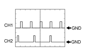 |
Waveform 1
| Tester Connection | CH1: A20-22 (PCON) - H3-6 (E1) CH2: A20-28 (PPOS) - H3-6 (E1) |
| Tool Setting | 10 V/DIV., 10 ms/DIV. |
| Vehicle Condition | Power switch on (IG) |
 |
Waveform 2
| Tester Connection | H3-14 (SPDI) - H3-6 (E1) |
| Tool Setting | 5 V/DIV., 10 ms/DIV. |
| Vehicle Condition | Driving at approx. 20 km/h (12 mph) |
Waveform 1 (Reference)
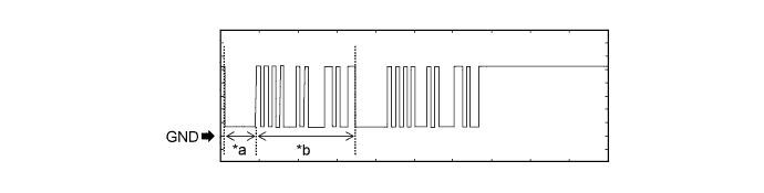
| *a | Approximately 160 ms | *b | Approximately 510 ms |
| Item | Content |
| Tester Connection | H4-20 (IMO) - H3-6 (E1) |
| Tool Setting | 2 V/DIV., 200 ms/DIV. |
| Condition | Within 3 seconds of hybrid control system start or within 3 seconds of power switch turned on (IG) after auxiliary battery cable disconnected and reconnected |
Waveform 2 (Reference)
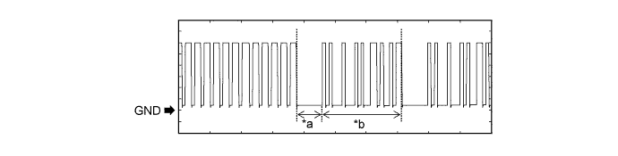
| *a | Approximately 160 ms | *b | Approximately 510 ms |
| Item | Content |
| Tester Connection | H4-21 (IMI) - H3-6 (E1) |
| Tool Setting | 2 V/DIV., 200 ms/DIV. |
| Condition | Power switch on (IG) |
| CHECK CERTIFICATION ECU (SMART KEY ECU ASSEMBLY) |
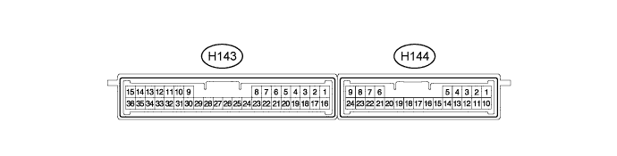
Disconnect the H143 certification ECU (smart key ECU assembly) connector.
Measure the voltage and resistance according to the value(s) in the table below.
| Terminal No. (Symbol) | Input/Output | Wiring Color | Terminal Description | Condition | Specified Condition | Related Data List Item |
| H143-15 (E) - Body ground | - | W-B - Body ground | Ground | Always | Below 1 Ω | - |
| H143-1 (+B) - H143-15 (E) | Input | B - W-B | +B power supply | Always | 11 to 14 V | - |
| H143-17 (CUTB) - H143-15 (E) | Input | Y - W-B | Dark current cut pin* | Always | 11 to 14 V | - |
Reconnect the H143 certification ECU (smart key ECU assembly) connector.
Measure the voltage according to the value(s) in the table below.
| Terminal No. (Symbol) | Input/Output | Wiring Color | Terminal Description | Condition | Specified Condition | Related Data List Item |
| H143-16 (IG) - H143-15 (E) | Input | BE - W-B | IG power supply | Power switch off → on (IG) | Below 1 V → 11 to 14 V | Power Switch |
| H143-7 (CLG5) - H143-15 (E) | Output | G - W-B | Output to No. 1 indoor electrical key antenna assembly (front floor) | Procedure:
| Pulse generation (See waveform 1) | Over Head + Front Room (key diagnostic mode) |
| H143-8 (CG5B) - H143-15 (E) | Output | R - W-B | Output to No. 1 indoor electrical key antenna assembly (front floor) (terminal on opposite side of component from CLG5 output terminal) | Procedure:
| Pulse generation (See waveform 1) | Over Head + Front Room (key diagnostic mode) |
| H143-24 (CLG6) - H143-15 (E) | Output | GR - W-B | Output to No. 2 indoor electrical key antenna assembly (rear floor) | Procedure:
| Pulse generation (See waveform 1) | Over Head + Rear Room (key diagnostic mode) |
| H143-25 (CG6B) - H143-15 (E) | Output | BR - W-B | Output to No. 2 indoor electrical key antenna assembly (rear floor) | Proceed:
| Pulse generation (See waveform 1) | Over Head + Rear Room (key diagnostic mode) |
| H143-26 (CLG7) - H143-15 (E) | Output | G - W-B | Output to No. 3 indoor electrical key antenna assembly (luggage compartment) | Proceed:
| Pulse generation (See waveform 1) | Over Head + Back Door (inside) (key diagnostic mode) |
| H143-27 (CG7B) - H143-15 (E) | Output | R - W-B | Output to No. 3 indoor electrical key antenna assembly (luggage compartment) | Proceed:
| Pulse generation (See waveform 1) | Over Head + Back Door (inside) (key diagnostic mode) |
| H144-5 (RCO) - H143-15 (E) | Output | R - W-B | Output to door control receiver (Power supply for door control receiver. Certification ECU (smart key ECU assembly) outputs 5 V when receiver starts operating.) | Procedure:
| Pulse generation (See waveform 2) | - |
| H144-15 (RDA) - H143-15 (E) | Input | Y - W-B | Door control receiver verifies data received from key. Receiver sends data to ECU and intermittently grounds 12 V signal from certification ECU (smart key ECU assembly). | Procedure:
| Pulse generation (See waveform 3) | - |
| H144-16 (RSSI) - H143-15 (E) | Input | V - W-B | Door control receiver sends signal to certification ECU (smart key ECU assembly) indicating whether electric waves (example: 312 MHz) from key are being received or not (receiver grounds 12 V signal from certification ECU (smart key ECU assembly)) | Procedure:
| Pulse generation (See waveform 4) | - |
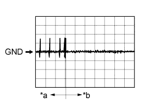 |
Using an oscilloscope, check waveform 1.
| *a | Door open |
| *b | After approximately 30 seconds from when the door is closed |
| Item | Content |
| Terminal No. (Symbol) |
|
| Tool Setting | 2 V/DIV., 500 ms/DIV. |
| Condition | Procedure:
|
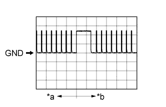 |
Using an oscilloscope, check waveform 2.
| *a | Before lock or unlock button of key pressed |
| *b | After lock or unlock button of key pressed |
| Item | Content |
| Terminal No. (Symbol) | H144-5 (RCO) - H143-15 (E) |
| Tool Setting | 2 V/DIV., 500 ms/DIV. |
| Condition | Procedure:
|
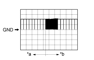 |
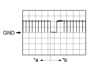
Using an oscilloscope, check waveform 3.
| *a | Before lock or unlock button of key pressed |
| *b | After lock or unlock button of key pressed |
| Item | Content |
| Terminal No. (Symbol) | H144-15 (RDA) - H143-15 (E) |
| Tool Setting | 5 V/DIV., 500 ms/DIV. |
| Condition | Procedure:
|
 |
Using an oscilloscope, check waveform 4.
| *a | Before lock or unlock button of key pressed |
| *b | After lock or unlock button of key pressed |
| Item | Content |
| Terminal No. (Symbol) | H144-16 (RSSI) - H143-15 (E) |
| Tool Setting | 5 V/DIV., 500 ms/DIV. |
| Condition | Procedure:
|
