DTC C1235/35 Foreign Object is Attached on Tip of Front Speed Sensor RH |
DTC C1236/36 Foreign Object is Attached on Tip of Front Speed Sensor LH |
DTC C1238/38 Foreign Object is Attached on Tip of Rear Speed Sensor RH |
DTC C1239/39 Foreign Object is Attached on Tip of Rear Speed Sensor LH |
DTC C1275/75 Abnormal Change in Output Signal of Front Speed Sensor RH (Test Mode DTC) |
DTC C1276/76 Abnormal Change in Output Signal of Front Speed Sensor LH (Test Mode DTC) |
DTC C1277/77 Abnormal Change in Output Signal of Rear Speed Sensor RH (Test Mode DTC) |
DTC C1278/78 Abnormal Change in Output Signal of Rear Speed Sensor LH (Test Mode DTC) |
| DTC Code | INF Code | DTC Detection Condition | Trouble Area |
| C1235/35 | 541 | Either of the following is detected:
|
|
| C1236/36 | 542 | Either of the following is detected:
|
|
| C1238/38 | 543 | Either of the following is detected:
|
|
| C1239/39 | 544 | Either of the following is detected:
|
|
| C1275/75 C1276/76 C1277/77 C1278/78 | - | Detected only during Test Mode. |
|
| 1.CHECK DTC |
Check that no speed sensor malfunction DTC is output (Click here).
| Result | Proceed to |
| DTCs (C1235/35 and/or C1236/36) are output | A |
| DTCs (C1238/38 and C1239/39) are output | B |
| Speed sensor malfunction DTCs (C1464/31, C1465/32, C1466/33 and/or C1467/34) are output | C |
|
| ||||
|
| ||||
| A | |
 |
| 2.CHECK FRONT SPEED SENSOR AND FRONT SPEED SENSOR ROTOR |
Remove the front speed sensor and front speed sensor rotor (Click here and Click here).
Check the speed sensor tip and speed sensor rotor.
|
| ||||
| OK | |
|
| 3.CHECK HARNESS AND CONNECTOR (SKID CONTROL ECU - FRONT SPEED SENSOR) |
Install the front speed sensor and front speed sensor rotor.
Make sure that there is no looseness at the locking part and the connecting part of the connectors.
Disconnect the skid control ECU connector and the front speed sensor connector.
Measure the resistance according to the value(s) in the table below.
| Tester Connection | Condition | Specified Condition |
| A61-18 (FR+) - A34-2 (FR+) | Always | Below 1 Ω |
| A61-18 (FR+) - Body ground | Always | 10 kΩ or higher |
| A61-5 (FR-) - A34-1 (FR-) | Always | Below 1 Ω |
| A61-5 (FR-) - Body ground | Always | 10 kΩ or higher |
| Tester Connection | Condition | Specified Condition |
| A61-31 (FL+) - A13-2 (FL+) | Always | Below 1 Ω |
| A61-31 (FL+) - Body ground | Always | 10 kΩ or higher |
| A61-32 (FL-) - A13-1 (FL-) | Always | Below 1 Ω |
| A61-32 (FL-) - Body ground | Always | 10 kΩ or higher |
|
| ||||
| OK | |
|
| 4.INSPECT SKID CONTROL ECU (SENSOR OUTPUT) |
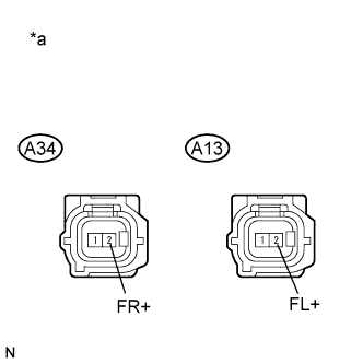 |
Reconnect the skid control ECU connector.
Turn the power switch on (IG).
Measure the voltage according to the value(s) in the table below.
| Tester Connection | Switch Condition | Specified Condition |
| A34-2 (FR+) - Body ground | Power switch on (IG) | 5.7 to 14 V |
| Tester Connection | Switch Condition | Specified Condition |
| A13-2 (FL+) - Body ground | Power switch on (IG) | 5.7 to 14 V |
| *a | Front view of wire harness connector (to Front Speed Sensor) |
| Result | Proceed to |
| OK | A |
| NG (for LHD) | B |
| NG (for RHD) | C |
|
| ||||
|
| ||||
| A | |
|
| 5.RECONFIRM DTC |
Turn the power switch off.
Reconnect the front speed sensor connector.
Clear the DTCs (Click here).
Turn the power switch on (READY).
Drive the vehicle at a speed of 20 km/h (12 mph) or more for at least 15 seconds.
Check if the same DTC is recorded (Click here).
| Result | Proceed to |
| DTCs (C1235/35 and/or C1236/36) are output | A |
| DTCs (C1235/35 and C1236/36) are not output | B |
|
| ||||
| A | |
|
| 6.REPLACE FRONT SPEED SENSOR |
Turn the power switch off.
Replace the front speed sensor (Click here).
| NEXT | |
|
| 7.RECONFIRM DTC |
Clear the DTCs (Click here).
Turn the power switch on (READY).
Drive the vehicle at a speed of 20 km/h (12 mph) or more for at least 15 seconds.
Check if the same DTC is recorded (Click here).
| Result | Proceed to |
| DTCs (C1235/35 and/or C1236/36) are output | A |
| DTCs (C1235/35 and C1236/36) are not output | B |
|
| ||||
| A | |
|
| 8.REPLACE FRONT SPEED SENSOR ROTOR |
Turn the power switch off.
Replace the front axle hub sub-assembly (front speed sensor rotor) (Click here).
| NEXT | |
|
| 9.RECONFIRM DTC |
Clear the DTCs (Click here).
Turn the power switch on (READY).
Drive the vehicle at a speed of 20 km/h (12 mph) or more for at least 15 seconds.
Check if the same DTC is recorded (Click here).
| Result | Proceed to |
| DTCs (C1235/35 and/or C1236/36) are output (for LHD) | A |
| DTCs (C1235/35 and/or C1236/36) are output (for RHD) | B |
| DTCs (C1235/35 and C1236/36) are not output | C |
|
| ||||
|
| ||||
| A | ||
 | ||
| ||
| 10.CHECK HARNESS AND CONNECTOR (SKID CONTROL SENSOR WIRE) |
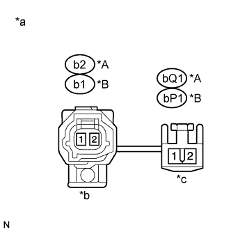 |
Make sure that there is no looseness at the locking part and the connecting part of the connectors.
Disconnect the rear speed sensor connector and the skid control sensor wire.
Measure the resistance according to the value(s) in the table below.
| Tester Connection | Condition | Specified Condition |
| b2-2 - bQ1-1 | Always | Below 1 Ω |
| b2-2 - bQ1-2 | Always | 10 kΩ or higher |
| b2-2 - Body ground | Always | 10 kΩ or higher |
| b2-1 - bQ1-2 | Always | Below 1 Ω |
| b2-1 - bQ1-1 | Always | 10 kΩ or higher |
| b2-1 - Body ground | Always | 10 kΩ or higher |
| Tester Connection | Condition | Specified Condition |
| b1-2 - bP1-1 | Always | Below 1 Ω |
| b1-2 - bP1-2 | Always | 10 kΩ or higher |
| b1-2 - Body ground | Always | 10 kΩ or higher |
| b1-1 - bP1-2 | Always | Below 1 Ω |
| b1-1 - bP1-1 | Always | 10 kΩ or higher |
| b1-1 - Body ground | Always | 10 kΩ or higher |
| *A | for RH |
| *B | for LH |
| *a | Front view of skid control sensor wire |
| *b | Front view of wire harness connector (to Sensor Side Connector) |
| *c | Front view of wire harness connector (to Vehicle Side Connector) |
|
| ||||
| OK | |
|
| 11.CHECK HARNESS AND CONNECTOR (SKID CONTROL ECU - SKID CONTROL SENSOR WIRE) |
Make sure that there is no looseness at the locking part and the connecting part of the connector.
Disconnect the skid control ECU connector.
Measure the resistance according to the value(s) in the table below.
| Tester Connection | Condition | Specified Condition |
| A61-22 (RR+) - bQ1-1 (RR+) | Always | Below 1 Ω |
| A61-22 (RR+) - Body ground | Always | 10 kΩ or higher |
| A61-9 (RR-) - bQ1-2 (RR-) | Always | Below 1 Ω |
| A61-9 (RR-) - Body ground | Always | 10 kΩ or higher |
| Tester Connection | Condition | Specified Condition |
| A61-20 (RL+) - bP1-1 (RL+) | Always | Below 1 Ω |
| A61-20 (RL+) - Body ground | Always | 10 kΩ or higher |
| A61-7 (RL-) - bP1-2 (RL-) | Always | Below 1 Ω |
| A61-7 (RL-) - Body ground | Always | 10 kΩ or higher |
|
| ||||
| OK | |
|
| 12.INSPECT SKID CONTROL ECU (SENSOR OUTPUT) |
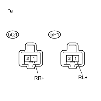 |
Reconnect the skid control ECU connector.
Turn the power switch on (IG).
Measure the voltage according to the value(s) in the table below.
| Tester Connection | Switch Condition | Specified Condition |
| bQ1-1 (RR+) - Body ground | Power switch on (IG) | 5.7 to 14 V |
| Tester Connection | Switch Condition | Specified Condition |
| bP1-1 (RL+) - Body ground | Power switch on (IG) | 5.7 to 14 V |
| *a | Front view of wire harness connector (to Skid Control Sensor Wire) |
| Result | Proceed to |
| OK | A |
| NG (for LHD) | B |
| NG (for RHD) | C |
|
| ||||
|
| ||||
| A | |
|
| 13.RECONFIRM DTC |
Turn the power switch off.
Reconnect the rear speed sensor connector and the skid control sensor wire.
Clear the DTCs (Click here).
Turn the power switch on (READY).
Drive the vehicle at a speed of 20 km/h (12 mph) or more for at least 15 seconds.
Check if the same DTC is recorded (Click here).
| Result | Proceed to |
| DTCs (C1238/38 and/or C1239/39) are output | A |
| DTCs (C1238/38 and C1239/39) are not output | B |
|
| ||||
| A | |
|
| 14.REPLACE REAR SPEED SENSOR AND REAR SPEED SENSOR ROTOR |
Turn the power switch off.
Replace the rear speed sensor and the rear axle hub and bearing assembly (rear speed sensor rotor) (Click here).
| NEXT | |
|
| 15.RECONFIRM DTC |
Clear the DTCs (Click here).
Turn the power switch on (READY).
Drive the vehicle at a speed of 20 km/h (12 mph) or more for at least 15 seconds.
Check if the same DTC is recorded (Click here).
| Result | Proceed to |
| DTCs (C1238/38 and/or C1239/39) are output (for LHD) | A |
| DTCs (C1238/38 and/or C1239/39) are output (for RHD) | B |
| DTCs (C1238/38 and C1239/39) are not output | C |
|
| ||||
|
| ||||
| A | ||
| ||
| ||


