ELECTRONICALLY CONTROLLED BRAKE SYSTEM > Skid Control Buzzer Circuit |
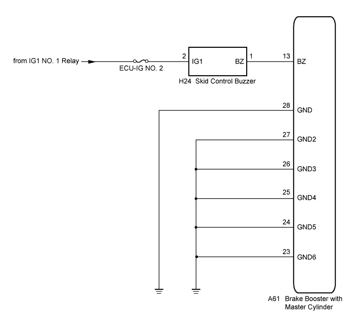
| 1.CHECK BUZZER OPERATION |
Confirm problem symptoms of the skid control buzzer according to the customer problem analysis.
| Result | Proceed to |
| Buzzer does not sound | A |
| Buzzer sounds constantly | B |
|
| ||||
| A | |
 |
| 2.PERFORM ACTIVE TEST USING INTELLIGENT TESTER (SKID CONTROL BUZZER) |
Connect the intelligent tester to the DLC3.
Turn the power switch on (IG).
Select the Active Test on the intelligent tester (Click here).
| Tester Display | Test Part | Control Range | Diagnostic Note |
| DSS Signal Buzzer | Skid control buzzer | Buzzer ON/OFF | Buzzer can be heard |
Check that the buzzer sounds/stops when turning the skid control buzzer on/off using the intelligent tester.
| Result | Proceed to |
| Buzzer does not sound | A |
| Buzzer sounds/stops | B |
|
| ||||
| A | |
|
| 3.INSPECT SKID CONTROL BUZZER (POWER SOURCE TERMINAL) |
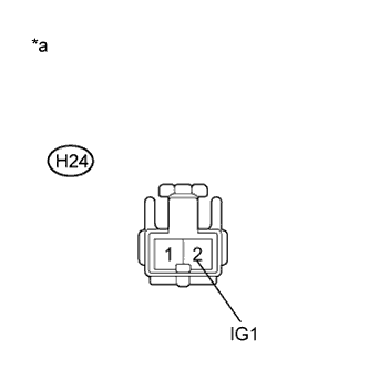 |
Turn the power switch off.
Disconnect the skid control buzzer connector.
Turn the power switch on (IG).
Measure the voltage according to the value(s) in the table below.
| Tester Connection | Switch Condition | Specified Condition |
| H24-2 (IG1) - Body ground | Power switch on (IG) | 11 to 14 V |
| *a | Front view of wire harness connector (to Skid Control Buzzer) |
|
| ||||
| OK | |
|
| 4.INSPECT SKID CONTROL BUZZER |
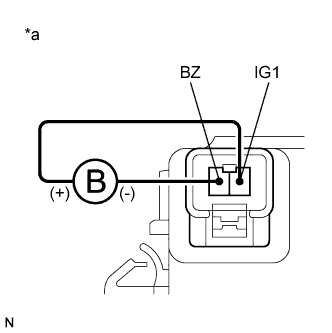 |
Turn the power switch off.
Connect a negative (-) lead from the battery to terminal 1 (BZ), and a positive (+) lead to terminal 2 (IG1) of the skid control buzzer, and then check that the buzzer sounds.
| *a | Component without harness connected (Skid Control Buzzer) |
| Result | Proceed to |
| OK | A |
| NG (for LHD) | B |
| NG (for RHD) | C |
|
| ||||
|
| ||||
| A | |
|
| 5.CHECK HARNESS AND CONNECTOR (SKID CONTROL ECU - SKID CONTROL BUZZER) |
Disconnect the skid control ECU connector 2 minutes after the power switch is turned off.
Measure the resistance according to the value(s) in the table below.
| Tester Connection | Condition | Specified Condition |
| A61-13 (BZ) - H24-1 (BZ) | Always | Below 1 Ω |
| A61-13 (BZ) - Body ground | Always | 10 kΩ or higher |
|
| ||||
| OK | |
|
| 6.INSPECT SKID CONTROL ECU (GND TERMINAL) |
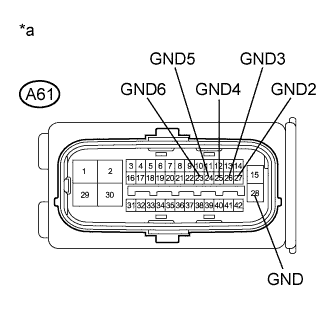 |
Measure the resistance according to the value(s) in the table below.
| Tester Connection | Condition | Specified Condition |
| A61-28 (GND) - Body ground | Always | Below 1 Ω |
| A61-27 (GND2) - Body ground | Always | Below 1 Ω |
| A61-26 (GND3) - Body ground | Always | Below 1 Ω |
| A61-25 (GND4) - Body ground | Always | Below 1 Ω |
| A61-24 (GND5) - Body ground | Always | Below 1 Ω |
| A61-23 (GND6) - Body ground | Always | Below 1 Ω |
| *a | Front view of wire harness connector (to Skid Control ECU) |
| Result | Proceed to |
| OK (for LHD) | A |
| OK (for RHD) | B |
| NG | C |
|
| ||||
|
| ||||
| A | ||
 | ||
| ||
| 7.INSPECT SKID CONTROL ECU |
Disconnect the skid control ECU connector.
Check that the skid control buzzer operation.
| Result | Proceed to |
| Buzzer stops (for LHD) | A |
| Buzzer stops (for RHD) | B |
| Buzzer sounds constantly | C |
|
| ||||
|
| ||||
| A | ||
| ||
| ||
| 8.REPLACE SKID CONTROL BUZZER |
Reconnect the skid control ECU connector.
Replace the skid control buzzer (Click here for LHD or Click here for RHD).
Check that the skid control buzzer operation.
| Result | Proceed to |
| Buzzer stops | A |
| Buzzer sounds constantly | B |
|
| ||||
| A | ||
| ||
| ||
| 9.CHECK IF CONNECTOR IS SECURELY CONNECTED |
Gently jiggle the connectors and wire harnesses and check the skid control buzzer operation.
| Result | Proceed to |
| Buzzer stops | A |
| Buzzer sounds constantly | B |
|
| ||||
| A | ||
| ||
| ||


