ENTRY AND START SYSTEM (for Entry Function) > Front Passenger Side Door Entry Lock and Unlock Functions do not Operate |
| 1.CHECK POWER DOOR LOCK OPERATION |
When the door control switch on the multiplex network master switch assembly is operated, check that the doors unlock and lock according to the switch operation (Click here).
|
| ||||
| OK | |
 |
| 2.READ VALUE USING INTELLIGENT TESTER (DOOR LOCK POSITION SWITCH) |
Connect the intelligent tester to the DLC3.
Turn the power switch on (IG).
Turn the intelligent tester on.
Enter the following menus: Body / Main Body / Data List.
Read the Data List according to the display on the intelligent tester.
| Tester Display | Measurement Item/Range | Normal Condition | Diagnostic Note |
| FL Door Lock Pos*1 | Front LH door lock position switch signal / UNLOCK or LOCK | UNLOCK: Front LH door unlocked LOCK: Front LH door locked | - |
| FR Door Lock Pos*2 | Front RH door lock position switch signal / UNLOCK or LOCK | UNLOCK: Front RH door unlocked LOCK: Front RH door locked | - |
|
| ||||
| OK | |
|
| 3.CHECK ELECTRICAL KEY ANTENNAS IN KEY DIAGNOSTIC MODE |
Check the following antennas in the key diagnostic mode (Click here).
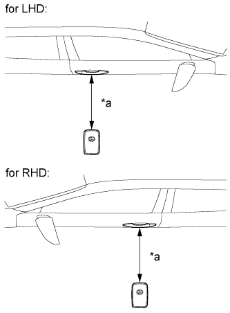 |
Check the electrical key antenna (for front passenger door):
| *a | 0.7 to 1 m (2.30 to 3.28 ft.) |
|
| ||||
| OK | ||
 | ||
| ||
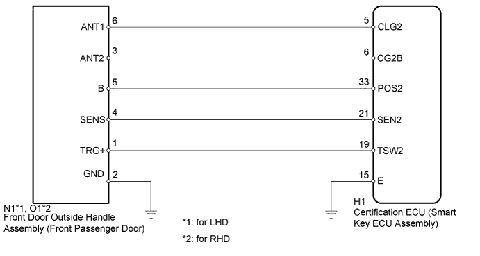
| 4.CHECK HARNESS AND CONNECTOR (FRONT DOOR OUTSIDE HANDLE - CERTIFICATION ECU) |
Disconnect the N1*1, O1*2 front door outside handle assembly (for front passenger door) connector.
Disconnect the H1 certification ECU (smart key ECU assembly) connector.
Measure the resistance according to the value(s) in the table below.
| Tester Connection | Condition | Specified Condition |
| N1-3 (ANT2) - H1-6 (CG2B) | Always | Below 1 Ω |
| N1-6 (ANT1) - H1-5 (CLG2) | Always | Below 1 Ω |
| N1-5 (B) - H1-33 (POS2) | Always | Below 1 Ω |
| N1-2 (GND) - Body ground | Always | Below 1 Ω |
| N1-3 (ANT2) or H1-6 (CG2B) - Body ground | Always | 10 kΩ or higher |
| N1-6 (ANT1) or H1-5 (CLG2) - Body ground | Always | 10 kΩ or higher |
| N1-5 (B) or H1-33 (POS2) - Body ground | Always | 10 kΩ or higher |
| Tester Connection | Condition | Specified Condition |
| O1-3 (ANT2) - H1-6 (CG2B) | Always | Below 1 Ω |
| O1-6 (ANT1) - H1-5 (CLG2) | Always | Below 1 Ω |
| O1-5 (B) - H1-33 (POS2) | Always | Below 1 Ω |
| O1-2 (GND) - Body ground | Always | Below 1 Ω |
| O1-3 (ANT2) or H1-6 (CG2B) - Body ground | Always | 10 kΩ or higher |
| O1-6 (ANT1) or H1-5 (CLG2) - Body ground | Always | 10 kΩ or higher |
| O1-5 (B) or H1-33 (POS2) - Body ground | Always | 10 kΩ or higher |
|
| ||||
| OK | |
|
| 5.CHECK CERTIFICATION ECU (SMART KEY ECU ASSEMBLY) (OUTPUT TO FRONT PASSENGER DOOR ELECTRICAL KEY ANTENNA) |
 |
Disconnect the N1*1, O1*2 front door outside handle assembly (for front passenger door) connector.
Connect the H1 certification ECU (smart key ECU assembly) connector.
Measure the voltage according to the value(s) in the table below.
| Tester Connection | Condition | Specified Condition |
| N1-5 (B) - Body ground | Power switch off → on (IG) | 9 to 14 V → Below 2 V |
| Tester Connection | Condition | Specified Condition |
| O1-5 (B) - Body ground | Power switch off → on (IG) | 9 to 14 V → Below 2 V |
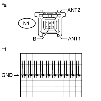
Using an oscilloscope, check the waveform.
| Tester Connection | Switch Condition | Tool Setting | Specified Condition |
| N1-3 (ANT2) - N1-6 (ANT1) | Procedure:
| 2 V/DIV., 500 ms/DIV. | Pulse generation (See waveform) |
| *1 | Waveform |
| *a | Front view of wire harness connector (to Front Door Outside Handle Assembly (for Front Passenger Door)) |
|
| ||||
| OK | |
|
| 6.REPLACE FRONT DOOR OUTSIDE HANDLE ASSEMBLY (FOR FRONT PASSENGER DOOR) |
Temporarily replace the front door outside handle assembly (for front passenger door) with a new or normally functioning one (Click here).
| NEXT | |
|
| 7.CHECK FRONT DOOR OUTSIDE HANDLE ASSEMBLY (OPERATION) |
Check that the entry functions operate normally (Click here).
|
| ||||
| OK | ||
| ||
| ||


