ENTRY AND START SYSTEM (for Entry Function) > Room Oscillator does not Recognize Key |
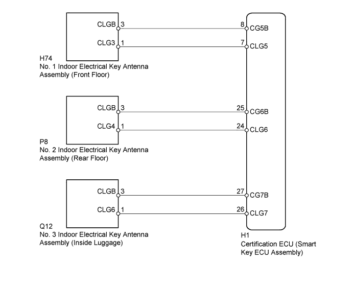
| 1.CHECK ENTRY AND START SYSTEM (FOR ENTRY FUNCTION) |
Check that the entry lock and unlock functions operate for each door (Click here).
|
| ||||
| OK | |
 |
| 2.CHECK ENTRY AND START SYSTEM (FOR START FUNCTION) |
 |
Remove the battery of the electrical key transmitter (Click here).
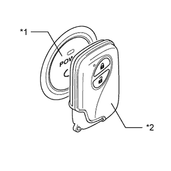
With the brake pedal depressed, touch the LEXUS mark of the key to the power switch.
When operating the power switch, check whether the hybrid control system starts.
| *1 | Power Switch |
| *2 | Electrical Key Transmitter |
|
| ||||
| OK | |
|
| 3.CHECK WAVE ENVIRONMENT |
Install the battery to the electrical key transmitter (Click here).
Bring the electrical key transmitter near the door control receiver and perform a entry and start system check.
| Result | Proceed to |
| System cannot be operated | A |
| System can be operated | B |
|
| ||||
| A | |
|
| 4.CHECK ELECTRICAL KEY ANTENNAS IN KEY DIAGNOSTIC MODE |
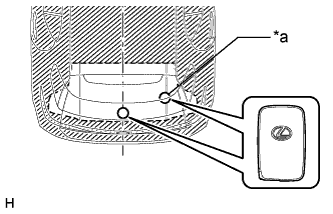
Check the following antennas in the key diagnostic mode (Click here).
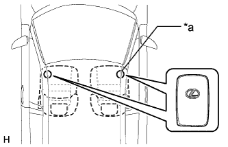 |
Check the No. 1 indoor electrical key antenna assembly (front floor).
| *a | Inspection Point |
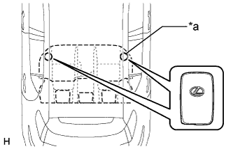 |
Check the No. 2 indoor electrical key antenna assembly (rear floor).
| *a | Inspection Point |
 |
Check the No. 3 indoor electrical key antenna assembly (inside luggage).
| *a | Inspection Point |
| Result | Proceed to |
| Front operation check fails | A |
| Rear operation check fails | B |
| Luggage operation check fails | C |
| Front, rear and luggage operation checks are normal | D |
|
| ||||
|
| ||||
|
| ||||
| A | |
|
| 5.CHECK HARNESS AND CONNECTOR (NO. 1 INDOOR ELECTRICAL KEY ANTENNA - CERTIFICATION ECU) |
Disconnect the H74 No. 1 indoor electrical key antenna assembly (front floor) connector.
Disconnect the H1 certification ECU (smart key ECU assembly) connector.
Measure the resistance according to the value(s) in the table below.
| Tester Connection | Condition | Specified Condition |
| H74-1 (CLG3) - H1-7 (CLG5) | Always | Below 1 Ω |
| H74-3 (CLGB) - H1-8 (CG5B) | Always | Below 1 Ω |
| H74-1 (CLG3) or H1-7 (CLG5) - Body ground | Always | 10 kΩ or higher |
| H74-3 (CLGB) or H1-8 (CG5B) - Body ground | Always | 10 kΩ or higher |
|
| ||||
| OK | |
|
| 6.CHECK CERTIFICATION ECU (SMART KEY ECU ASSEMBLY) (OUTPUT TO NO. 1 INDOOR ELECTRICAL KEY ANTENNA [FRONT FLOOR]) |
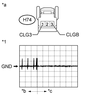 |
Disconnect the H74 No. 1 indoor electrical key antenna assembly (front floor) connector.
Connect the H1 certification ECU (smart key ECU assembly) connector.
Using an oscilloscope, check the waveform.
| Tester Connection | Switch Condition | Tool Setting | Specified Condition |
| H74-1 (CLG3) - H74-3 (CLGB) | Procedure:
| 2 V/DIV., 500 ms/DIV. | Pulse generation (See waveform) |
| *1 | Waveform |
| *a | Front view of wire harness connector (to No. 1 Indoor Electrical Key Antenna [Front Floor]) |
| *b | Door open |
| *c | After approximately 30 seconds from when the door is closed |
|
| ||||
| OK | |
|
| 7.REPLACE NO. 1 INDOOR ELECTRICAL KEY ANTENNA ASSEMBLY (FRONT FLOOR) |
Temporarily replace the No. 1 indoor electrical key antenna assembly (front floor) with a new or normally functioning one (Click here).
| NEXT | |
|
| 8.CHECK ELECTRICAL KEY ANTENNA IN KEY DIAGNOSTIC MODE |
Check the following antenna in the key diagnostic mode (Click here).
|
Check the No. 1 indoor electrical key antenna assembly (front floor).
When the electrical key transmitter is at the inspection point, check that the wireless door lock buzzer sounds.
| *a | Inspection Point |
|
| ||||
| OK | ||
 | ||
| ||
| 9.CHECK HARNESS AND CONNECTOR (NO. 2 INDOOR ELECTRICAL KEY ANTENNA - CERTIFICATION ECU) |
Disconnect the P8 No. 2 indoor electrical key antenna assembly (rear floor) connector.
Disconnect the H1 certification ECU (smart key ECU assembly) connector.
Measure the resistance according to the value(s) in the table below.
| Tester Connection | Condition | Specified Condition |
| P8-1 (CLG4) - H1-24 (CLG6) | Always | Below 1 Ω |
| P8-3 (CLGB) - H1-25 (CG6B) | Always | Below 1 Ω |
| P8-1 (CLG4) or H1-24 (CLG6) - Body ground | Always | 10 kΩ or higher |
| P8-3 (CLGB) or H1-25 (CG6B) - Body ground | Always | 10 kΩ or higher |
|
| ||||
| OK | |
|
| 10.CHECK CERTIFICATION ECU (SMART KEY ECU ASSEMBLY) (OUTPUT TO NO. 2 INDOOR ELECTRICAL KEY ANTENNA [REAR FLOOR]) |
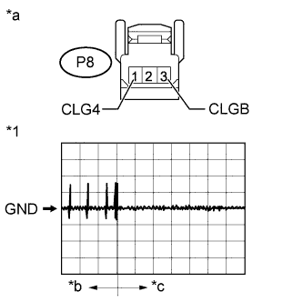 |
Disconnect the P8 No. 2 indoor electrical key antenna assembly (rear floor) connector.
Connect the H1 certification ECU (smart key ECU assembly) connector.
Using an oscilloscope, check the waveform.
| Tester Connection | Switch Condition | Tool Setting | Specified Condition |
| P8-1 (CLG4) - P8-3 (CLGB) | Procedure:
| 2 V/DIV., 500 ms/DIV. | Pulse generation (See waveform) |
| *1 | Waveform |
| *a | Front view of wire harness connector (to No. 2 Indoor Electrical Key Antenna [Rear Floor]) |
| *b | Door open |
| *c | After approximately 30 seconds from when the door is closed |
|
| ||||
| OK | |
|
| 11.REPLACE NO. 2 INDOOR ELECTRICAL KEY ANTENNA ASSEMBLY (REAR FLOOR) |
Temporarily replace the No. 2 indoor electrical key antenna assembly (rear floor) with a new or normally functioning one (Click here).
| NEXT | |
|
| 12.CHECK ELECTRICAL KEY ANTENNA IN KEY DIAGNOSTIC MODE |
Check the following antenna in the key diagnostic mode (Click here).
|
Check the No. 2 indoor electrical key antenna assembly (rear floor).
When the electrical key transmitter is at the inspection point, check that the wireless door lock buzzer sounds.
| *a | Inspection Point |
|
| ||||
| OK | ||
| ||
| ||
| 13.CHECK HARNESS AND CONNECTOR (NO. 3 INDOOR ELECTRICAL KEY ANTENNA - CERTIFICATION ECU) |
Disconnect the Q12 No. 3 indoor electrical key antenna assembly (inside luggage) connector.
Disconnect the H1 certification ECU (smart key ECU assembly) connector.
Measure the resistance according to the value(s) in the table below.
| Tester Connection | Condition | Specified Condition |
| Q12-1 (CLG6) - H1-26 (CLG7) | Always | Below 1 Ω |
| Q12-3 (CLGB) - H1-27 (CG7B) | Always | Below 1 Ω |
| Q12-1 (CLG6) or H1-26 (CLG7) - Body ground | Always | 10 kΩ or higher |
| Q12-3 (CLGB) or H1-27 (CG7B) - Body ground | Always | 10 kΩ or higher |
|
| ||||
| OK | |
|
| 14.CHECK CERTIFICATION ECU (SMART KEY ECU ASSEMBLY) (OUTPUT TO INDOOR NO. 3 ELECTRICAL KEY ANTENNA) |
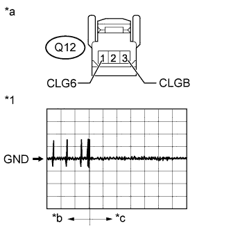 |
Disconnect the Q12 No. 3 indoor electrical key antenna assembly (inside luggage) connector.
Connect the H1 certification ECU (smart key ECU assembly) connector.
Using an oscilloscope, check the waveform.
| Tester Connection | Switch Condition | Tool Setting | Specified Condition |
| Q12-1 (CLG6) - Q12-3 (CLGB) | Procedure:
| 2 V/DIV., 500 ms/DIV. | Pulse generation (See waveform) |
| *1 | Waveform |
| *a | Front view of wire harness connector (to No. 3 Indoor Electrical Key Antenna [Rear Floor]) |
| *b | Door open |
| *c | After approximately 30 seconds from when the door is closed |
|
| ||||
| OK | |
|
| 15.REPLACE NO. 3 INDOOR ELECTRICAL KEY ANTENNA ASSEMBLY (INSIDE LUGGAGE) |
Temporarily replace the No. 3 indoor electrical key antenna assembly (inside luggage) with a new or normally functioning one (Click here).
| NEXT | |
|
| 16.CHECK ELECTRICAL KEY ANTENNA IN KEY DIAGNOSTIC MODE |
Check the following antenna in the key diagnostic mode (Click here).
|
Check the No. 3 indoor electrical key antenna assembly (inside luggage).
When the electrical key transmitter is at the inspection point, check that the wireless door lock buzzer sounds.
| *a | Inspection Point |
|
| ||||
| OK | ||
| ||
| ||


