CAN COMMUNICATION SYSTEM > TERMINALS OF ECU |
| CAN NO. 1 JUNCTION CONNECTOR (for LHD) |
Check the CAN No. 1 junction connector (Engine room main wire side).
Connection diagram
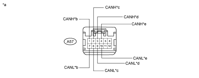
| *a | Front view of wire harness connector (to CAN No. 1 Junction Connector) | *b | to ECM (for V1 bus) |
| *c | to Skid Control ECU (Brake Booster with Master Cylinder Assembly) (for V1 bus) | *d | to Skid Control ECU (Brake Booster with Master Cylinder Assembly) (for Power management bus) |
| *e | to ECM (for Power management bus) | - | - |
Check the connection diagram of the components which are connected to the CAN No. 1 junction connector.
| Terminal No. (Symbol) | Wiring Color | Connected to (Applicable Bus) |
| A57-1 (CANH) | P | ECM (for V1 bus) |
| A57-7 (CANL) | V | |
| A57-2 (CANH) | LG | Skid control ECU (Brake booster with master cylinder assembly) (for V1 bus) |
| A57-8 (CANL) | L | |
| A57-3 (CANH) | P | Skid control ECU (Brake booster with master cylinder assembly) (for Power management bus) |
| A57-9 (CANL) | V | |
| A57-4 (CANH) | B | ECM (for Power management bus) |
| A57-10 (CANL) | W |
Check the CAN No. 1 junction connector (Instrument panel wire side).
Connection diagram
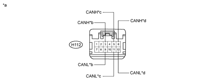
| *a | Front view of wire harness connector (to CAN No. 1 Junction Connector) | *b | to CAN No. 5 Junction Connector (for Power management bus) |
| *c | Main body ECU (Multiplex Network Body ECU) (for V1 bus) | *d | to CAN No. 2 Junction Connector (for V1 bus) |
Check the connection diagram of the components which are connected to the CAN No. 1 junction connector.
| Terminal No. (Symbol) | Wiring Color | Connected to |
| H112-3 (CANH) | B | CAN No. 5 junction connector (for Power management bus) |
| H112-9 (CANL) | W | |
| H112-5 (CANH) | BR | Main body ECU (Multiplex network body ECU) (for V1 bus) |
| H112-11 (CANL) | W | |
| H112-6 (CANH) | R | CAN No. 2 junction connector (for V1 bus) |
| H112-12 (CANL) | W |
| CAN NO. 1 JUNCTION CONNECTOR (for RHD) |
Check the CAN No. 1 junction connector (Engine room main wire side).
Connection diagram
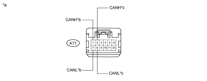
| *a | Front view of wire harness connector (to CAN No. 1 Junction Connector) | *b | to ECM |
| *c | to Transmission Control ECU Assembly | - | - |
Check the connection diagram of the components which are connected to the CAN No. 1 junction connector.
| Terminal No. (Symbol) | Wiring Color | Connected to |
| A71-1 (CANH) | P | ECM |
| A71-7 (CANL) | V | |
| A71-2 (CANH) | Y | Transmission control ECU assembly |
| A71-8 (CANL) | BR |
Check the CAN No. 1 junction connector (Instrument panel wire side).
Connection diagram
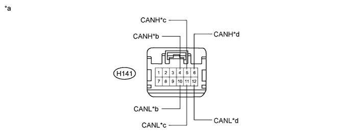
| *a | Front view of wire harness connector (to CAN No. 1 Junction Connector) | *b | to Power Management Control ECU |
| *c | to Main body ECU (Multiplex Network Body ECU) | *d | to CAN No. 2 Junction Connector |
Check the connection diagram of the components which are connected to the CAN No. 1 junction connector.
| Terminal No. (Symbol) | Wiring Color | Connected to |
| H141-4 (CANH) | P | Power Management Control ECU |
| H141-10 (CANL) | V | |
| H141-5 (CANH) | BR | Main body ECU (Multiplex network body ECU) |
| H141-11 (CANL) | W | |
| H141-6 (CANH) | R | CAN No. 2 junction connector |
| H141-12 (CANL) | W |
| CAN NO. 2 JUNCTION CONNECTOR |
Check the CAN No. 2 junction connector (Instrument panel connector holder front side).
Connection diagram
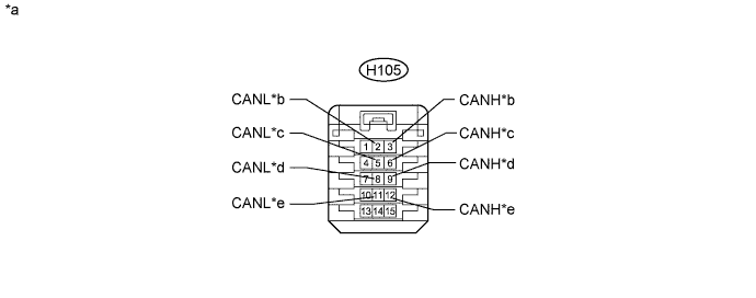
| *a | Front view of wire harness connector (to CAN No. 2 Junction Connector) | *b | to Steering Angle Sensor (Spiral Cable with Sensor Sub-assembly) |
| *c | to Certification ECU (Smart Key ECU Assembly) | *d | to Airbag Sensor Assembly |
| *e | to Yaw Rate and Acceleration Sensor | - | - |
Check the connection diagram of the components which are connected to the CAN No. 2 junction connector.
| Terminal No. (Symbol) | Wiring Color | Connected to |
| H105-3 (CANH) | L | Steering angle sensor (Spiral cable with sensor sub-assembly) |
| H105-2 (CANL) | B | |
| H105-6 (CANH) | L | Certification ECU (Smart key ECU assembly) |
| H105-5 (CANL) | B | |
| H105-9 (CANH) | L | Airbag sensor assembly |
| H105-8 (CANL) | B | |
| H105-12 (CANH) | L | Yaw rate and acceleration sensor |
| H105-11 (CANL) | B |
Check the CAN No. 2 junction connector (Instrument panel connector holder rear side).
Connection diagram
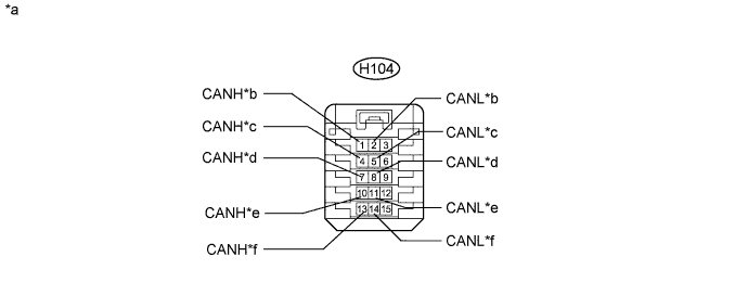
| *a | Front view of wire harness connector (to CAN No. 2 Junction Connector) | *b | to CAN No. 1 Junction Connector |
| *c | to CAN No. 3 Junction Connector | *d | to DLC3 |
| *e | to Power Steering ECU Assembly | *f | to Navigation ECU (to Display and Navigation Module Display)*1 to Navigation ECU (to Navigation Computer Sub-assembly)*2 |
Check the connection diagram of the components which are connected to the CAN No. 2 junction connector.
| Terminal No. (Symbol) | Wiring Color | Connected to |
| H104-1 (CANH) | R | CAN No. 1 junction connector |
| H104-2 (CANL) | W | |
| H104-4 (CANH) | R | CAN No. 3 junction connector |
| H104-5 (CANL) | W | |
| H104-7 (CANH) | R | DLC3 |
| H104-8 (CANL) | W | |
| H104-10 (CANH) | R | Power steering ECU assembly |
| H104-11 (CANL) | W | |
| H104-13 (CANH) | R | Navigation ECU (to Display and navigation module display)*1 Navigation ECU (to Navigation computer sub-assembly)*2 |
| H104-14 (CANL) | W |
| CAN NO. 3 JUNCTION CONNECTOR (for LHD) |
Check the CAN No. 3 junction connector (Engine room main wire side).
Connection diagram
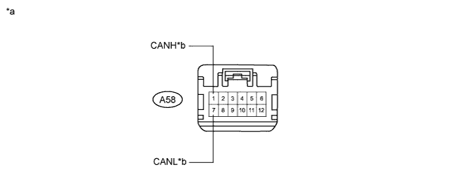
| *a | Front view of wire harness connector (to CAN No. 3 Junction Connector) | *b | to Transmission Control ECU Assembly |
Check the connection diagram of the components which are connected to the CAN No. 3 junction connector.
| Terminal No. (Symbol) | Wiring Color | Connected to |
| A58-1 (CANH) | Y | Transmission control ECU assembly |
| A58-7 (CANL) | BR |
Check the CAN No. 3 junction connector (Instrument panel wire side).
Connection diagram
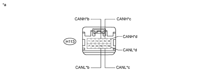
| *a | Front view of wire harness connector (to CAN No. 3 Junction Connector) | *b | to Power Management Control ECU |
| *c | to CAN No. 2 Junction Connector | *d | to Combination Meter Assembly |
Check the connection diagram of the components which are connected to the CAN No. 3 junction connector.
| Terminal No. (Symbol) | Wiring Color | Connected to |
| H113-4 (CANH) | P | Power management control ECU |
| H113-10 (CANL) | V | |
| H113-5 (CANH) | R | CAN No. 2 junction connector |
| H113-11 (CANL) | W | |
| H113-6 (CANH) | P | Combination meter assembly |
| H113-12 (CANL) | V |
| CAN NO. 3 JUNCTION CONNECTOR (for RHD) |
Check the CAN No. 3 junction connector (Engine room main wire side).
Connection diagram
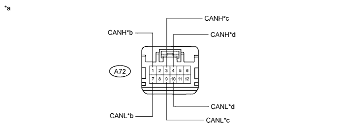
| *a | Front view of wire harness connector (to CAN No. 3 Junction Connector) | *b | to Skid Control ECU (Brake Booster with Master Cylinder Assembly) (for V1 bus) |
| *c | to Skid Control ECU (Brake Booster with Master Cylinder Assembly) (for Power management bus) | *d | to ECM (for Power management bus) |
Check the connection diagram of the components which are connected to the CAN No. 3 junction connector.
| Terminal No. (Symbol) | Wiring Color | Connected to |
| A72-1 (CANH) | LG | Skid control ECU (Brake booster with master cylinder assembly) (for V1 bus) |
| A72-7 (CANL) | L | |
| A72-3 (CANH) | P | Skid control ECU (Brake booster with master cylinder assembly) (for Power management bus) |
| A72-9 (CANL) | V | |
| A72-4 (CANH) | B | ECM (for Power management bus) |
| A72-10 (CANL) | W |
Check the CAN No. 3 junction connector (Instrument panel wire side).
Connection diagram
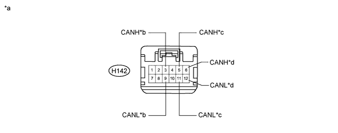
| *a | Front view of wire harness connector (to CAN No. 3 Junction Connector) | *b | to CAN No. 5 Junction Connector (for Power management bus) |
| *c | to CAN No. 2 Junction Connector (for V1 bus) | *d | to Combination Meter Assembly (for V1 bus) |
Check the connection diagram of the components which are connected to the CAN No. 3 junction connector.
| Terminal No. (Symbol) | Wiring Color | Connected to |
| H142-3 (CANH) | B | CAN No. 5 junction connector (for Power management bus) |
| H142-9 (CANL) | W | |
| H142-5 (CANH) | R | CAN No. 2 junction connector (for V1 bus) |
| H142-11 (CANL) | W | |
| H142-6 (CANH) | P | Combination meter assembly (for V1 bus) |
| H142-12 (CANL) | V |
| CAN NO. 4 JUNCTION CONNECTOR (for V2 Bus) |
Check the CAN No. 4 junction connector.
Connection diagram
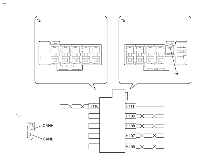
| *1 | CAN No. 4 Junction Connector | - | - |
| *a | Junction Connector B Side | *b | Junction Connector A Side |
| *c | Earth Terminal | *d | Front view of wire harness connector (to CAN No. 4 Junction Connector) |
Check the connection diagram of the components which are connected to the CAN No. 4 junction connector.
| Terminal No. (Symbol) | Wiring Color | Connected to |
| H110-1 (CANH) | P | Parking assist ECU |
| H110-2 (CANL) | B |
| Terminal No. (Symbol) | Wiring Color | Connected to |
| H111-1 (GND) | W-B | Body ground |
| H106-1 (CANH) | R | Power management control ECU |
| H106-2 (CANL) | B | |
| H107-1 (CANH) | G | Clearance warning ECU assembly |
| H107-2 (CANL) | B | |
| H108-1 (CANH) | L | Driving support ECU assembly |
| H108-2 (CANL) | B | |
| H109-1 (CANH) | Y | Seat belt control ECU |
| H109-2 (CANL) | B |
| CAN NO. 5 JUNCTION CONNECTOR (for Power Management Bus) |
Check the CAN No. 5 junction connector (Instrument panel connector holder front side).
Connection diagram
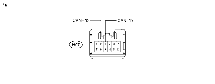
| *a | Front view of wire harness connector (to CAN No. 5 Junction Connector) | *b | to CAN No. 1 Junction Connector |
Check the connection diagram of the components which are connected to the CAN No. 5 junction connector.
| Terminal No. (Symbol) | Wiring Color | Connected to |
| H97-2 (CANH) | B | CAN No. 1 junction connector |
| H97-3 (CANL) | W |
Check the CAN No. 5 junction connector (Instrument panel connector holder rear side).
Connection diagram
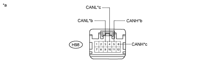
| *a | Front view of wire harness connector (to CAN No. 5 Junction Connector) | *b | to Air Conditioning Amplifier Assembly |
| *c | to Power Management Control ECU | - | - |
Check the connection diagram of the components which are connected to the CAN No. 5 junction connector.
| Terminal No. (Symbol) | Wiring Color | Connected to |
| H98-5 (CANH) | Y | Air conditioning amplifier assembly |
| H98-3 (CANL) | BR | |
| H98-6 (CANH) | LG | Power management control ECU |
| H98-4 (CANL) | L |
| CAN NO. 6 JUNCTION CONNECTOR (for MS Bus) |
Check the CAN No. 6 junction connector.
Connection diagram
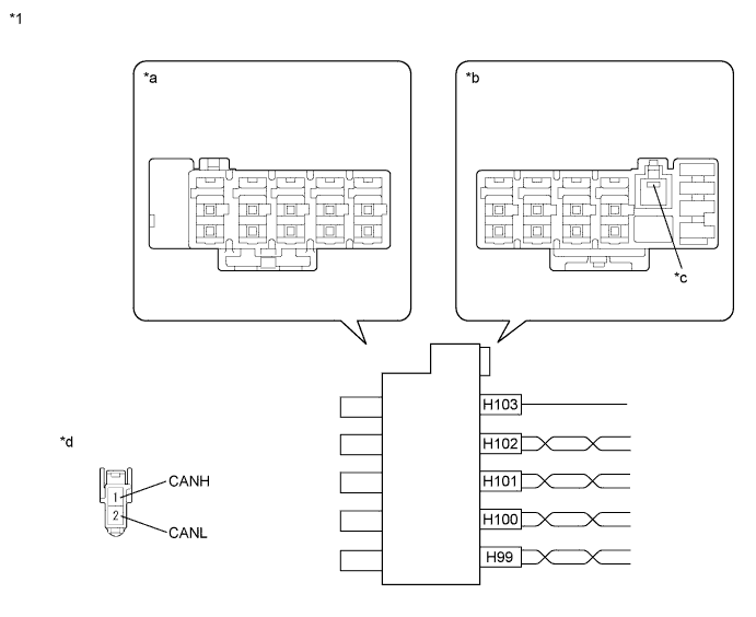
| *1 | CAN No. 6 Junction Connector | - | - |
| *a | Junction Connector B Side | *b | Junction Connector A Side |
| *c | Earth Terminal | *d | Front view of wire harness connector (to CAN No. 6 Junction Connector) |
Check the connection diagram of the components which are connected to the CAN No. 6 junction connector.
| Terminal No. (Symbol) | Wiring Color | Connected to |
| H103-1 (GND) | W-B | Body ground |
| H99-1 (CANH) | R |
|
| H99-2 (CANL) | W | |
| H100-1 (CANH) | G | Main body ECU (Multiplex network body ECU) |
| H100-2 (CANL) | W | |
| H101-1 (CANH) | L | Position control ECU and switch assembly |
| H101-2 (CANL) | W | |
| H102-1 (CANH) | Y |
|
| H102-2 (CANL) | W |
| DLC3 |
Measure the resistance according to the value(s) in the table below.
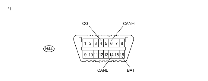
| Terminal No. (Symbol) | Wiring Color | Terminal Description | Condition | Specified Condition |
| H44-6 (CANH) - H44-14 (CANL) | R - W | HIGH-level CAN bus line - LOW-level CAN bus line | Power switch off | 54 to 69 Ω |
| H44-6 (CANH) - H44-4 (CG) | R - G | HIGH-level CAN bus line - Ground | Power switch off | 200 Ω or higher |
| H44-14 (CANL) - H44-4 (CG) | W - G | LOW-level CAN bus line - Ground | Power switch off | 200 Ω or higher |
| H44-6 (CANH) - H44-16 (BAT) | R - R | HIGH-level CAN bus line - Battery positive (+) | Cable disconnected from negative (-) auxiliary battery terminal | 6 kΩ or higher |
| H44-14 (CANL) - H44-16 (BAT) | W - R | LOW-level CAN bus line - Battery positive (+) | Cable disconnected from negative (-) auxiliary battery terminal | 6 kΩ or higher |
| *1 | DLC3 | - | - |
| ECM |
Disconnect the ECM connectors.
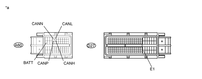
| *a | Front view of wire harness connector (to ECM) | - | - |
Measure the resistance according to the value(s) in the table below.
| Terminal No. (Symbol) | Wiring Color | Terminal Description | Condition | Specified Condition |
| A60-13 (CANH) - A60-5 (CANL) | P - V | HIGH-level CAN bus line - LOW-level CAN bus line | Power switch off | 108 to 132 Ω |
| A60-13 (CANH) - D27-104 (E1) | P - BR | HIGH-level CAN bus line - Ground | Power switch off | 200 Ω or higher |
| A60-5 (CANL) - D27-104 (E1) | V - BR | LOW-level CAN bus line - Ground | Power switch off | 200 Ω or higher |
| A60-13 (CANH) - A60-20 (BATT) | P - R | HIGH-level CAN bus line - Battery positive (+) | Cable disconnected from negative (-) auxiliary battery terminal | 6 kΩ or higher |
| A60-5 (CANL) - A60-20 (BATT) | V - R | LOW-level CAN bus line - Battery positive (+) | Cable disconnected from negative (-) auxiliary battery terminal | 6 kΩ or higher |
| Terminal No. (Symbol) | Wiring Color | Terminal Description | Condition | Specified Condition |
| A60-12 (CANP) - A60-4 (CANN) | B - W | HIGH-level CAN bus line - LOW-level CAN bus line | Power switch off | 108 to 132 Ω |
| A60-12 (CANP) - D27-104 (E1) | B - BR | HIGH-level CAN bus line - Ground | Power switch off | 200 Ω or higher |
| A60-4 (CANN) - D27-104 (E1) | W - BR | LOW-level CAN bus line - Ground | Power switch off | 200 Ω or higher |
| A60-12 (CANP) - A60-20 (BATT) | B - R | HIGH-level CAN bus line - Battery positive (+) | Cable disconnected from negative (-) auxiliary battery terminal | 6 kΩ or higher |
| A60-4 (CANN) - A60-20 (BATT) | W - R | LOW-level CAN bus line - Battery positive (+) | Cable disconnected from negative (-) auxiliary battery terminal | 6 kΩ or higher |
| COMBINATION METER ASSEMBLY |
Disconnect the combination meter assembly connector.
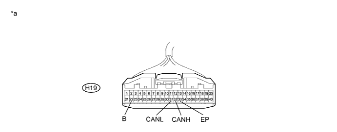
| *a | Front view of wire harness connector (to Combination Meter Assembly) | - | - |
Measure the resistance according to the value(s) in the table below.
| Terminal No. (Symbol) | Wiring Color | Terminal Description | Condition | Specified Condition |
| H19-32 (CANH) - H19-31 (CANL) | P - V | HIGH-level CAN bus line - LOW-level CAN bus line | Power switch off | 108 to 132 Ω |
| H19-32 (CANH) - H19-33 (EP) | P - W-B | HIGH-level CAN bus line - Ground | Power switch off | 200 Ω or higher |
| H19-31 (CANL) - H19-33 (EP) | V - W-B | LOW-level CAN bus line - Ground | Power switch off | 200 Ω or higher |
| H19-32 (CANH) - H19-22 (B) | P - V | HIGH-level CAN bus line - Battery positive (+) | Cable disconnected from negative (-) auxiliary battery terminal | 6 kΩ or higher |
| H19-31 (CANL) - H19-22 (B) | V - V | LOW-level CAN bus line - Battery positive (+) | Cable disconnected from negative (-) auxiliary battery terminal | 6 kΩ or higher |
| POWER MANAGEMENT CONTROL ECU |
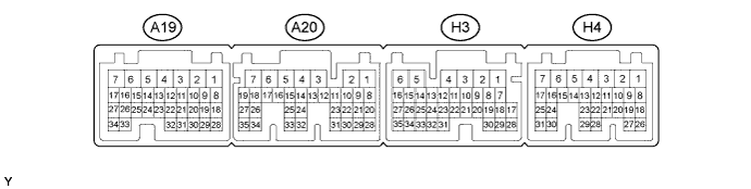
V1 Bus Branch Lines
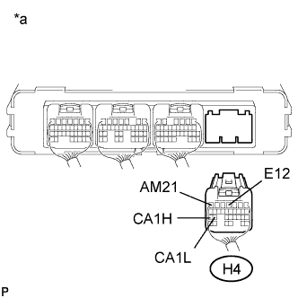 |
Disconnect the power management control ECU connector.
| *a | Rear view of wire harness connector (to Power Management Control ECU) |
Measure the resistance according to the value(s) in the table below.
| Terminal No. (Symbol) | Wiring Color | Terminal Description | Condition | Specified Condition |
| H4-25 (CA1H) - H4-24 (CA1L) | P - V | HIGH-level CAN bus line - LOW-level CAN bus line | Power switch off | 54 to 69 Ω |
| H4-25 (CA1H) - H4-4 (E12) | P - W-B | HIGH-level CAN bus line - Ground | Power switch off | 200 Ω or higher |
| H4-24 (CA1L) - H4-4 (E12) | V - W-B | LOW-level CAN bus line - Ground | Power switch off | 200 Ω or higher |
| H4-25 (CA1H) - H4-7 (AM21) | P - W | HIGH-level CAN bus line - Battery positive (+) | Cable disconnected from negative (-) auxiliary battery terminal | 6 kΩ or higher |
| H4-24 (CA1L) - H4-7 (AM21) | V - W | LOW-level CAN bus line - Battery positive (+) | Cable disconnected from negative (-) auxiliary battery terminal | 6 kΩ or higher |
V2 Bus Main Lines
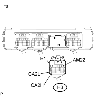 |
Disconnect the power management control ECU connector.
| *a | Rear view of wire harness connector (to Power Management Control ECU) |
Measure the resistance according to the value(s) in the table below.
| Terminal No. (Symbol) | Wiring Color | Terminal Description | Condition | Specified Condition |
| H3-34 (CA2H) - H3-35 (CA2L) | R - B | HIGH-level CAN bus line - LOW-level CAN bus line | Power switch off | 108 to 132 Ω |
| H3-34 (CA2H) - H3-6 (E1) | R - W-B | HIGH-level CAN bus line - Ground | Power switch off | 200 Ω or higher |
| H3-35 (CA2L) - H3-6 (E1) | B - W-B | LOW-level CAN bus line - Ground | Power switch off | 200 Ω or higher |
| H3-34 (CA2H) - H3-1 (AM22) | R - W | HIGH-level CAN bus line - Battery positive (+) | Cable disconnected from negative (-) auxiliary battery terminal | 6 kΩ or higher |
| H3-35 (CA2L) - H3-1 (AM22) | B - W | LOW-level CAN bus line - Battery positive (+) | Cable disconnected from negative (-) auxiliary battery terminal | 6 kΩ or higher |
Power Management Bus Main Lines
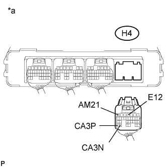 |
Disconnect the power management control ECU connector.
| *a | Rear view of wire harness connector (to Power Management Control ECU) |
Measure the resistance according to the value(s) in the table below.
| Terminal No. (Symbol) | Wiring Color | Terminal Description | Condition | Specified Condition |
| H4-31 (CA3P) - H4-30 (CA3N) | LG - L | HIGH-level CAN bus line - LOW-level CAN bus line | Power switch off | 108 to 132 Ω |
| H4-31 (CA3P) - H4-4 (E12) | LG - W-B | HIGH-level CAN bus line - Ground | Power switch off | 200 Ω or higher |
| H4-30 (CA3N) - H4-4 (E12) | L - W-B | LOW-level CAN bus line - Ground | Power switch off | 200 Ω or higher |
| H4-31 (CA3P) - H4-7 (AM21) | LG - W | HIGH-level CAN bus line - Battery positive (+) | Cable disconnected from negative (-) auxiliary battery terminal | 6 kΩ or higher |
| H4-30 (CA3N) - H4-7 (AM21) | L - W | LOW-level CAN bus line - Battery positive (+) | Cable disconnected from negative (-) auxiliary battery terminal | 6 kΩ or higher |
| MAIN BODY ECU (MULTIPLEX NETWORK BODY ECU) |
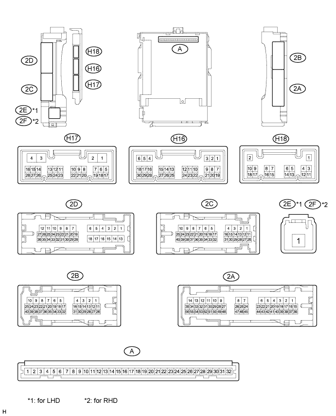
Disconnect the main body ECU (multiplex network body ECU) connectors.
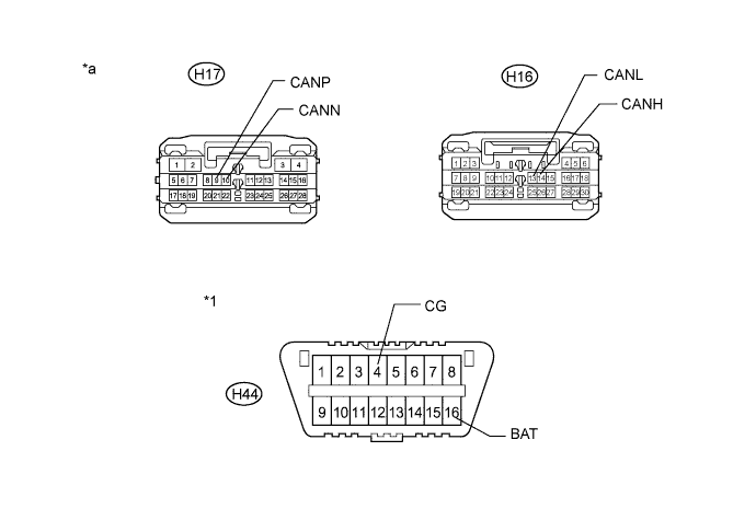
| *1 | DLC3 | - | - |
| *a | Front view of wire harness connector (to Multiplex Network Body ECU) | - | - |
Measure the resistance according to the value(s) in the table below.
| Terminal No. (Symbol) | Wiring Color | Terminal Description | Condition | Specified Condition |
| H16-14 (CANH) - H16-13 (CANL) | BR - W | HIGH-level CAN bus line - LOW-level CAN bus line | Power switch off | 54 to 69 Ω |
| H16-14 (CANH) - H44-4 (CG) | BR - G | HIGH-level CAN bus line - Ground | Power switch off | 200 Ω or higher |
| H16-13 (CANL) - H44-4 (CG) | W - G | LOW-level CAN bus line - Ground | Power switch off | 200 Ω or higher |
| H16-14 (CANH) - H44-16 (BAT) | BR - R | HIGH-level CAN bus line - Battery positive (+) | Cable disconnected from negative (-) auxiliary battery terminal | 6 kΩ or higher |
| H16-13 (CANL) - H44-16 (BAT) | W - R | LOW-level CAN bus line - Battery positive (+) | Cable disconnected from negative (-) auxiliary battery terminal | 6 kΩ or higher |
| Terminal No. (Symbol) | Wiring Color | Terminal Description | Condition | Specified Condition |
| H17-9 (CANP) - H17-10 (CANN) | G - W | HIGH-level CAN bus line - LOW-level CAN bus line | Power switch off | 108 to 132 Ω |
| H17-9 (CANP) - H44-4 (CG) | G - G | HIGH-level CAN bus line - Ground | Power switch off | 200 Ω or higher |
| H17-10 (CANN) - H44-4 (CG) | W - G | LOW-level CAN bus line - Ground | Power switch off | 200 Ω or higher |
| H17-9 (CANP) - H44-16 (BAT) | G - R | HIGH-level CAN bus line - Battery positive (+) | Cable disconnected from negative (-) auxiliary battery terminal | 6 kΩ or higher |
| H17-10 (CANN) - H44-16 (BAT) | W - R | LOW-level CAN bus line - Battery positive (+) | Cable disconnected from negative (-) auxiliary battery terminal | 6 kΩ or higher |
| SKID CONTROL ECU (BRAKE BOOSTER WITH MASTER CYLINDER ASSEMBLY) |
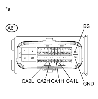 |
Disconnect the skid control ECU (brake booster with master cylinder assembly) connector.
| *a | Front view of wire harness connector (to Skid Control ECU) |
Measure the resistance according to the value(s) in the table below.
| Terminal No. (Symbol) | Wiring Color | Terminal Description | Condition | Specified Condition |
| A61-37 (CA1H) - A61-38 (CA1L) | LG - L | HIGH-level CAN bus line - LOW-level CAN bus line | Power switch off | 54 to 69 Ω |
| A61-37 (CA1H) - A61-28 (GND) | LG - W | HIGH-level CAN bus line - Ground | Power switch off | 200 Ω or higher |
| A61-38 (CA1L) - A61-28 (GND) | L - W | LOW-level CAN bus line - Ground | Power switch off | 200 Ω or higher |
| A61-37 (CA1H) - A61-15 (BS) | LG - B | HIGH-level CAN bus line - Battery positive (+) | Cable disconnected from negative (-) auxiliary battery terminal | 6 kΩ or higher |
| A61-38 (CA1L) - A61-15 (BS) | L - B | LOW-level CAN bus line - Battery positive (+) | Cable disconnected from negative (-) auxiliary battery terminal | 6 kΩ or higher |
| Terminal No. (Symbol) | Wiring Color | Terminal Description | Condition | Specified Condition |
| A61-35 (CA2H) - A61-34 (CA2L) | P - V | HIGH-level CAN bus line - LOW-level CAN bus line | Power switch off | 54 to 69 Ω |
| A61-35 (CA2H) - A61-28 (GND) | P - W | HIGH-level CAN bus line - Ground | Power switch off | 200 Ω or higher |
| A61-34 (CA2L) - A61-28 (GND) | V - W | LOW-level CAN bus line - Ground | Power switch off | 200 Ω or higher |
| A61-35 (CA2H) - A61-15 (BS) | P - B | HIGH-level CAN bus line - Battery positive (+) | Cable disconnected from negative (-) auxiliary battery terminal | 6 kΩ or higher |
| A61-34 (CA2L) - A61-15 (BS) | V - B | LOW-level CAN bus line - Battery positive (+) | Cable disconnected from negative (-) auxiliary battery terminal | 6 kΩ or higher |
| STEERING ANGLE SENSOR (SPIRAL CABLE WITH SENSOR SUB-ASSEMBLY) |
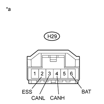 |
Disconnect the steering angle sensor connector.
| *a | Front view of wire harness connector (to Steering Angle Sensor) |
Measure the resistance according to the value(s) in the table below.
| Terminal No. (Symbol) | Wiring Color | Terminal Description | Condition | Specified Condition |
| H29-4 (CANH) - H29-3 (CANL) | L - B | HIGH-level CAN bus line - LOW-level CAN bus line | Power switch off | 54 to 69 Ω |
| H29-4 (CANH) - H29-2 (ESS) | L - W-B | HIGH-level CAN bus line - Ground | Power switch off | 200 Ω or higher |
| H29-3 (CANL) - H29-2 (ESS) | B - W-B | LOW-level CAN bus line - Ground | Power switch off | 200 Ω or higher |
| H29-4 (CANH) - H29-6 (BAT) | L - G | HIGH-level CAN bus line - Battery positive (+) | Cable disconnected from negative (-) auxiliary battery terminal | 6 kΩ or higher |
| H29-3 (CANL) - H29-6 (BAT) | B - G | LOW-level CAN bus line - Battery positive (+) | Cable disconnected from negative (-) auxiliary battery terminal | 6 kΩ or higher |
| YAW RATE AND ACCELERATION SENSOR |
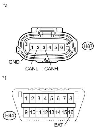 |
Disconnect the yaw rate and acceleration sensor connector.
| *1 | DLC3 |
| *a | Front view of wire harness connector (to Yaw Rate and Acceleration Sensor) |
Measure the resistance according to the value(s) in the table below.
| Terminal No. (Symbol) | Wiring Color | Terminal Description | Condition | Specified Condition |
| H87-3 (CANH) - H87-2 (CANL) | L - B | HIGH-level CAN bus line - LOW-level CAN bus line | Power switch off | 54 to 69 Ω |
| H87-3 (CANH) - H87-1 (GND) | L - W-B | HIGH-level CAN bus line - Ground | Power switch off | 200 Ω or higher |
| H87-2 (CANL) - H87-1 (GND) | B - W-B | LOW-level CAN bus line - Ground | Power switch off | 200 Ω or higher |
| H87-3 (CANH) - H44-16 (BAT) | L - R | HIGH-level CAN bus line - Battery positive (+) | Cable disconnected from negative (-) auxiliary battery terminal | 6 kΩ or higher |
| H87-2 (CANL) - H44-16 (BAT) | B - R | LOW-level CAN bus line - Battery positive (+) | Cable disconnected from negative (-) auxiliary battery terminal | 6 kΩ or higher |
| POWER STEERING ECU ASSEMBLY |
Disconnect the power steering ECU assembly connectors.
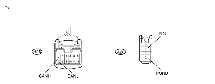
| *a | Front view of wire harness connector (to Power Steering ECU Assembly) | - | - |
Measure the resistance according to the value(s) in the table below.
| Terminal No. (Symbol) | Wiring Color | Terminal Description | Condition | Specified Condition |
| H25-1 (CANH) - H25-7 (CANL) | R - W | HIGH-level CAN bus line - LOW-level CAN bus line | Power switch off | 54 to 69 Ω |
| H25-1 (CANH) - A26-2 (PGND) | R - W-B | HIGH-level CAN bus line - Ground | Power switch off | 200 Ω or higher |
| H25-7 (CANL) - A26-2 (PGND) | W - W-B | LOW-level CAN bus line - Ground | Power switch off | 200 Ω or higher |
| H25-1 (CANH) - A26-1 (PIG) | R - W | HIGH-level CAN bus line - Battery positive (+) | Cable disconnected from negative (-) auxiliary battery terminal | 6 kΩ or higher |
| H25-7 (CANL) - A26-1 (PIG) | W - W | LOW-level CAN bus line - Battery positive (+) | Cable disconnected from negative (-) auxiliary battery terminal | 6 kΩ or higher |
| AIRBAG SENSOR ASSEMBLY |
Disconnect the airbag sensor assembly connector.
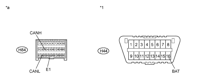
| *1 | DLC3 | - | - |
| *a | Front view of wire harness connector (to Airbag Sensor Assembly) | - | - |
Measure the resistance according to the value(s) in the table below.
| Terminal No. (Symbol) | Wiring Color | Terminal Description | Condition | Specified Condition |
| H84-13 (CANH) - H84-22 (CANL) | L - B | HIGH-level CAN bus line - LOW-level CAN bus line | Power switch off | 54 to 69 Ω |
| H84-13 (CANH) - H84-25 (E1) | L - W-B | HIGH-level CAN bus line - Ground | Power switch off | 200 Ω or higher |
| H84-22 (CANL) - H84-25 (E1) | B - W-B | LOW-level CAN bus line - Ground | Power switch off | 200 Ω or higher |
| H84-13 (CANH) - H44-16 (BAT) | L - R | CAN communication line H - Battery positive (+) | Cable disconnected from negative (-) auxiliary battery terminal | 6 kΩ or higher |
| H84-22 (CANL) - H44-16 (BAT) | B - R | CAN communication line L - Battery positive (+) | Cable disconnected from negative (-) auxiliary battery terminal | 6 kΩ or higher |
| CERTIFICATION ECU (SMART KEY ECU ASSEMBLY) |
Disconnect the smart key ECU assembly connector.
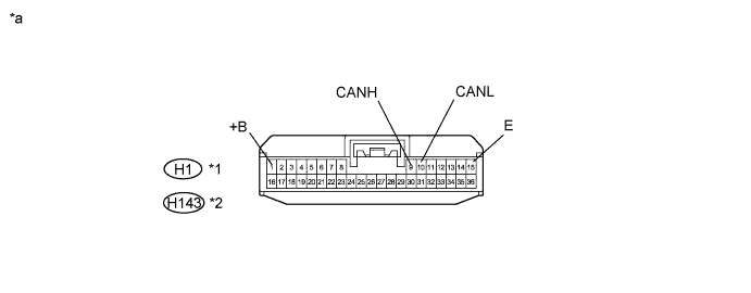
| *1 | w/ Entry Function | *2 | w/o Entry Function |
| *a | Front view of wire harness connector (to Certification ECU) | - | - |
Measure the resistance according to the value(s) in the table below.
| Terminal No. (Symbol) | Wiring Color | Terminal Description | Condition | Specified Condition |
| H1-9 (CANH) - H1-10 (CANL)*1 H143-9 (CANH) - H143-10 (CANL)*2 | L - B | HIGH-level CAN bus line - LOW-level CAN bus line | Power switch off | 54 to 69 Ω |
| H1-9 (CANH) - H1-15 (E)*1 H143-9 (CANH) - H143-15 (E)*2 | L - W-B | HIGH-level CAN bus line - Ground | Power switch off | 200 Ω or higher |
| H1-10 (CANL) - H1-15 (E)*1 H143-10 (CANL) - H143-15 (E)*2 | B - W-B | LOW-level CAN bus line - Ground | Power switch off | 200 Ω or higher |
| H1-9 (CANH) - H1-1 (+B)*1 H143-9 (CANH) - H143-1 (+B)*2 | L - B | HIGH-level CAN bus line - Battery positive (+) | Cable disconnected from negative (-) auxiliary battery terminal | 6 kΩ or higher |
| H1-10 (CANL) - H1-1 (+B)*1 H143-10 (CANL) - H143-1 (+B)*2 | B - B | LOW-level CAN bus line - Battery positive (+) | Cable disconnected from negative (-) auxiliary battery terminal | 6 kΩ or higher |
| TRANSMISSION CONTROL ECU ASSEMBLY |
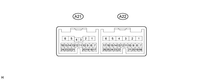
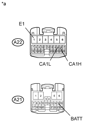 |
Disconnect the transmission control assembly ECU connectors.
| *a | Front view of wire harness connector (to Transmission Control ECU Assembly) |
Measure the resistance according to the value(s) in the table below.
| Terminal No. (Symbol) | Wiring Color | Terminal Description | Condition | Specified Condition |
| A22-16 (CA1H) - A22-15 (CA1L) | Y - BR | HIGH-level CAN bus line - LOW-level CAN bus line | Power switch off | 54 to 69 Ω |
| A22-16 (CA1H) - A22-1 (E1) | Y - BR | HIGH-level CAN bus line - Ground | Power switch off | 200 Ω or higher |
| A22-15 (CA1L) - A22-1 (E1) | BR - BR | LOW-level CAN bus line - Ground | Power switch off | 200 Ω or higher |
| A22-16 (CA1H) - A21-15 (BATT) | Y - SB | HIGH-level CAN bus line - Battery positive (+) | Cable disconnected from negative (-) auxiliary battery terminal | 6 kΩ or higher |
| A22-15 (CA1L) - A21-15 (BATT) | BR - SB | LOW-level CAN bus line - Battery positive (+) | Cable disconnected from negative (-) auxiliary battery terminal | 6 kΩ or higher |
| NAVIGATION ECU (DISPLAY AND NAVIGATION MODULE DISPLAY) (w/ Navigation System for DVD) |
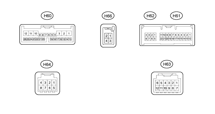
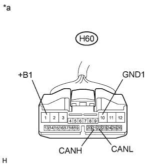 |
Disconnect the navigation ECU (display and navigation module display) connector.
| *a | Front view of wire harness connector (to Display and Navigation Module Display) |
Measure the resistance according to the value(s) in the table below.
| Terminal No. (Symbol) | Wiring Color | Terminal Description | Condition | Specified Condition |
| H60-21 (CANH) - H60-22 (CANL) | R - W | HIGH-level CAN bus line - LOW-level CAN bus line | Power switch off | 54 to 69 Ω |
| H60-21 (CANH) - H60-10 (GND1) | R - W-B | HIGH-level CAN bus line - Ground | Power switch off | 200 Ω or higher |
| H60-22 (CANL) - H60-10 (GND1) | W - W-B | LOW-level CAN bus line - Ground | Power switch off | 200 Ω or higher |
| H60-21 (CANH) - H60-1 (+B1) | R - V | HIGH-level CAN bus line - Battery positive (+) | Cable disconnected from negative (-) auxiliary battery terminal | 6 kΩ or higher |
| H60-22 (CANL) - H60-1 (+B1) | W - V | LOW-level CAN bus line - Battery positive (+) | Cable disconnected from negative (-) auxiliary battery terminal | 6 kΩ or higher |
| NAVIGATION ECU (NAVIGATION COMPUTER SUB-ASSEMBLY) (w/ Navigation System for HDD) |
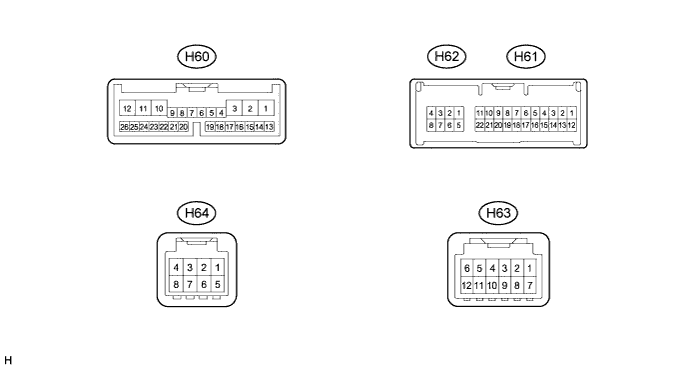
|
Disconnect the navigation ECU (navigation computer sub-assembly) connector.
| *a | Front view of wire harness connector (to Navigation Computer Sub-Assembly) |
Measure the resistance according to the value(s) in the table below.
| Terminal No. (Symbol) | Wiring Color | Terminal Description | Condition | Specified Condition |
| H60-21 (CANH) - H60-22 (CANL) | R - W | HIGH-level CAN bus line - LOW-level CAN bus line | Power switch off | 54 to 69 Ω |
| H60-21 (CANH) - H60-10 (GND1) | R - W-B | HIGH-level CAN bus line - Ground | Power switch off | 200 Ω or higher |
| H60-22 (CANL) - H60-10 (GND1) | W - W-B | LOW-level CAN bus line - Ground | Power switch off | 200 Ω or higher |
| H60-21 (CANH) - H60-1 (+B1) | R - V | HIGH-level CAN bus line - Battery positive (+) | Cable disconnected from negative (-) auxiliary battery terminal | 6 kΩ or higher |
| H60-22 (CANL) - H60-1 (+B1) | W - V | LOW-level CAN bus line - Battery positive (+) | Cable disconnected from negative (-) auxiliary battery terminal | 6 kΩ or higher |
| AIR CONDITIONING AMPLIFIER ASSEMBLY |
Disconnect the air conditioning amplifier assembly connector.
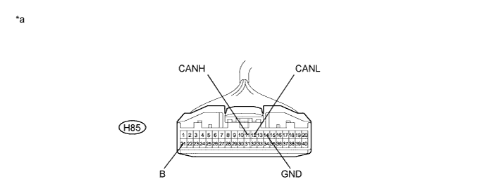
| *a | Front view of wire harness connector (to Air Conditioning Amplifier Assembly) | - | - |
Measure the resistance according to the value(s) in the table below.
| Terminal No. (Symbol) | Wiring Color | Terminal Description | Condition | Specified Condition |
| H85-11 (CANH) - H85-12 (CANL) | Y - BR | HIGH-level CAN bus line - LOW-level CAN bus line | Power switch off | 54 to 69 Ω |
| H85-11 (CANH) - H85-14 (GND) | Y - W-B | HIGH-level CAN bus line - Ground | Power switch off | 200 Ω or higher |
| H85-12 (CANL) - H85-14 (GND) | BR - W-B | LOW-level CAN bus line - Ground | Power switch off | 200 Ω or higher |
| H85-11 (CANH) - H85-21 (B) | Y - Y | HIGH-level CAN bus line - Battery positive (+) | Cable disconnected from negative (-) auxiliary battery terminal | 6 kΩ or higher |
| H85-12 (CANL) - H85-21 (B) | BR - Y | LOW-level CAN bus line - Battery positive (+) | Cable disconnected from negative (-) auxiliary battery terminal | 6 kΩ or higher |
| SEAT BELT CONTROL ECU (w/ Pre-crash Safety System) |
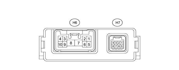
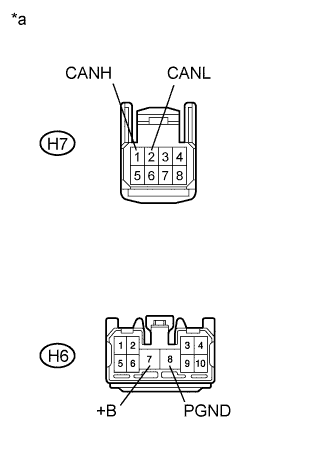 |
Disconnect the seat belt control ECU connectors.
| *a | Front view of wire harness connector (to Seat Belt Control ECU) |
Measure the resistance according to the value(s) in the table below.
| Terminal No. (Symbol) | Wiring Color | Terminal Description | Condition | Specified Condition |
| H7-1 (CANH) - H7-2 (CANL) | Y - B | HIGH-level CAN bus line - LOW-level CAN bus line | Power switch off | 54 to 69 Ω |
| H7-1 (CANH) - H6-8 (PGND) | Y - W-B | HIGH-level CAN bus line - Ground | Power switch off | 200 Ω or higher |
| H7-2 (CANL) - H6-8 (PGND) | B - W-B | LOW-level CAN bus line - Ground | Power switch off | 200 Ω or higher |
| H7-1 (CANH) - H6-7 (+B) | Y - B | HIGH-level CAN bus line - Battery positive (+) | Cable disconnected from negative (-) auxiliary battery terminal | 6 kΩ or higher |
| H7-2 (CANL) - H6-7 (+B) | B - B | LOW-level CAN bus line - Battery positive (+) | Cable disconnected from negative (-) auxiliary battery terminal | 6 kΩ or higher |
| DRIVING SUPPORT ECU ASSEMBLY (w/ Dynamic Radar Cruise Control System) |
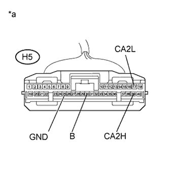 |
Disconnect the driving support ECU assembly connector.
| *a | Front view of wire harness connector (to Driving Support ECU Assembly) |
Measure the resistance according to the value(s) in the table below.
| Terminal No. (Symbol) | Wiring Color | Terminal Description | Condition | Specified Condition |
| H5-39 (CA2H) - H5-17 (CA2L) | L - B | HIGH-level CAN bus line - LOW-level CAN bus line | Power switch off | 54 to 69 Ω |
| H5-39 (CA2H) - H5-25 (GND) | L - W-B | HIGH-level CAN bus line - Ground | Power switch off | 200 Ω or higher |
| H5-17 (CA2L) - H5-25 (GND) | B - W-B | LOW-level CAN bus line - Ground | Power switch off | 200 Ω or higher |
| H5-39 (CA2H) - H5-30 (B) | L - BE | HIGH-level CAN bus line - Battery positive (+) | Cable disconnected from negative (-) auxiliary battery terminal | 6 kΩ or higher |
| H5-17 (CA2L) - H5-30 (B) | B - BE | LOW-level CAN bus line - Battery positive (+) | Cable disconnected from negative (-) auxiliary battery terminal | 6 kΩ or higher |
| OUTER MIRROR CONTROL ECU ASSEMBLY (for Driver side) |
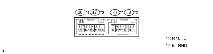
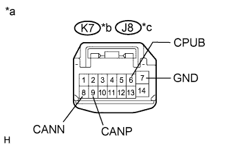 |
Disconnect the outer mirror control ECU assembly connector.
| *a | Front view of wire harness (to Outer Mirror Control ECU Assembly) |
| *b | for LHD |
| *c | for RHD |
Measure the resistance according to the value(s) in the table below.
| Terminal No. (Symbol) | Wiring Color | Terminal Description | Condition | Specified Condition |
| K7-9 (CANP) - K7-8 (CANN) | B - W | HIGH-level CAN bus line - LOW-level CAN bus line | Power switch off | 54 to 69 Ω |
| K7-9 (CANP) - K7-7 (GND) | B - W-B | HIGH-level CAN bus line - Ground | Power switch off | 200 Ω or higher |
| K7-8 (CANN) - K7-7 (GND) | W - W-B | LOW-level CAN bus line - Ground | Power switch off | 200 Ω or higher |
| K7-9 (CANP) - K7-6 (CPUB) | B - LG | HIGH-level CAN bus line - Battery positive (+) | Cable disconnected from negative (-) auxiliary battery terminal | 6 kΩ or higher |
| K7-8 (CANN) - K7-6 (CPUB) | W - LG | LOW-level CAN bus line - Battery positive (+) | Cable disconnected from negative (-) auxiliary battery terminal | 6 kΩ or higher |
| Terminal No. (Symbol) | Wiring Color | Terminal Description | Condition | Specified Condition |
| J8-9 (CANP) - J8-8 (CANN) | W - Y | HIGH-level CAN bus line - LOW-level CAN bus line | Power switch off | 54 to 69 Ω |
| J8-9 (CANP) - J8-7 (GND) | W - W-B | HIGH-level CAN bus line - Ground | Power switch off | 200 Ω or higher |
| J8-8 (CANN) - J8-7 (GND) | Y - W-B | LOW-level CAN bus line - Ground | Power switch off | 200 Ω or higher |
| J8-9 (CANP) - J8-6 (CPUB) | W - LG | HIGH-level CAN bus line - Battery positive (+) | Cable disconnected from negative (-) auxiliary battery terminal | 6 kΩ or higher |
| J8-8 (CANN) - J8-6 (CPUB) | Y - LG | LOW-level CAN bus line - Battery positive (+) | Cable disconnected from negative (-) auxiliary battery terminal | 6 kΩ or higher |
| OUTER MIRROR CONTROL ECU ASSEMBLY (for Front passenger side) |
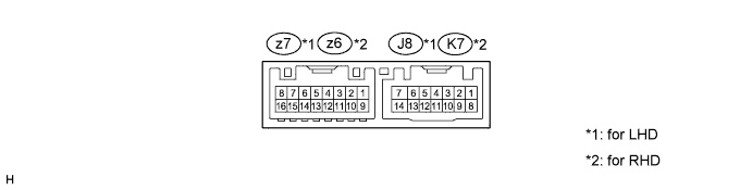
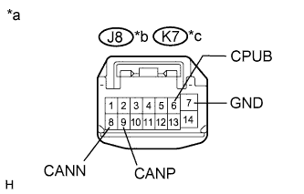 |
Disconnect the outer mirror control ECU assembly connector.
| *a | Front view of wire harness (to Outer Mirror Control ECU Assembly) |
| *b | for LHD |
| *c | for RHD |
Measure the resistance according to the value(s) in the table below.
| Terminal No. (Symbol) | Wiring Color | Terminal Description | Condition | Specified Condition |
| J8-9 (CANP) - J8-8 (CANN) | W - Y | HIGH-level CAN bus line - LOW-level CAN bus line | Power switch off | 54 to 69 Ω |
| J8-9 (CANP) - J8-7 (GND) | W - W-B | HIGH-level CAN bus line - Ground | Power switch off | 200 Ω or higher |
| J8-8 (CANN) - J8-7 (GND) | Y - W-B | LOW-level CAN bus line - Ground | Power switch off | 200 Ω or higher |
| J8-9 (CANP) - J8-6 (CPUB) | W - LG | HIGH-level CAN bus line - Battery positive (+) | Cable disconnected from negative (-) auxiliary battery terminal | 6 kΩ or higher |
| J8-8 (CANN) - J8-6 (CPUB) | Y - LG | LOW-level CAN bus line - Battery positive (+) | Cable disconnected from negative (-) auxiliary battery terminal | 6 kΩ or higher |
| Terminal No. (Symbol) | Wiring Color | Terminal Description | Condition | Specified Condition |
| K7-9 (CANP) - K7-8 (CANN) | B - W | HIGH-level CAN bus line - LOW-level CAN bus line | Power switch off | 54 to 69 Ω |
| K7-9 (CANP) - K7-7 (GND) | B - W-B | HIGH-level CAN bus line - Ground | Power switch off | 200 Ω or higher |
| K7-8 (CANN) - K7-7 (GND) | W - W-B | LOW-level CAN bus line - Ground | Power switch off | 200 Ω or higher |
| K7-9 (CANP) - K7-6 (CPUB) | B - LG | HIGH-level CAN bus line - Battery positive (+) | Cable disconnected from negative (-) auxiliary battery terminal | 6 kΩ or higher |
| K7-8 (CANN) - K7-6 (CPUB) | W - LG | LOW-level CAN bus line - Battery positive (+) | Cable disconnected from negative (-) auxiliary battery terminal | 6 kΩ or higher |
| POSITION CONTROL ECU AND SWITCH ASSEMBLY (w/ Seat Position Memory for LHD) |

Disconnect the connectors of the position control ECU and switch assembly.
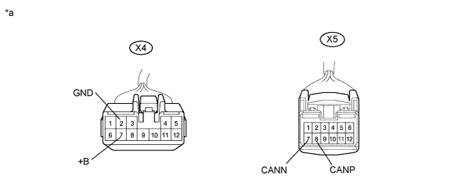
| *a | Front view of wire harness connector (to Position Control ECU and Switch Assembly) | - | - |
Measure the resistance according to the value(s) in the table below.
| Terminal No. (Symbol) | Wiring Color | Terminal Description | Condition | Specified Condition |
| X5-8 (CANP) - X5-7 (CANN) | L - W | HIGH-level CAN bus line - LOW-level CAN bus line | Power switch off | 54 to 69 Ω |
| X5-8 (CANP) - X4-2 (GND) | L - W-B | HIGH-level CAN bus line - Ground | Power switch off | 200 Ω or higher |
| X5-7 (CANN) - X4-2 (GND) | W - W-B | LOW-level CAN bus line - Ground | Power switch off | 200 Ω or higher |
| X5-8 (CANP) - X4-7 (+B) | L - W | HIGH-level CAN bus line - Battery positive (+) | Cable disconnected from negative (-) auxiliary battery terminal | 6 kΩ or higher |
| X5-7 (CANN) - X4-7 (+B) | W - W | LOW-level CAN bus line - Battery positive (+) | Cable disconnected from negative (-) auxiliary battery terminal | 6 kΩ or higher |
| POSITION CONTROL ECU AND SWITCH ASSEMBLY (w/ Seat Position Memory for RHD) |

Disconnect the connectors of the position control ECU and switch assembly.
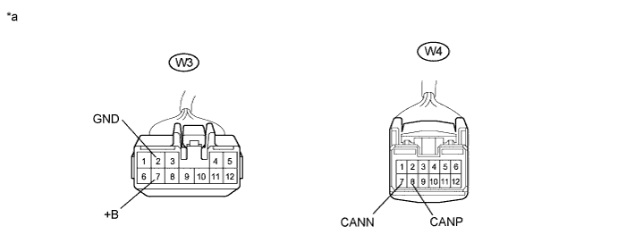
| *a | Front view of wire harness connector (to Position Control ECU and Switch Assembly) | - | - |
Measure the resistance according to the value(s) in the table below.
| Terminal No. (Symbol) | Wiring Color | Terminal Description | Condition | Specified Condition |
| W4-8 (CANP) - W4-7 (CANN) | L - W | HIGH-level CAN bus line - LOW-level CAN bus line | Power switch off | 54 to 69 Ω |
| W4-8 (CANP) - W3-2 (GND) | L - W-B | HIGH-level CAN bus line - Ground | Power switch off | 200 Ω or higher |
| W4-7 (CANN) - W3-2 (GND) | W - W-B | LOW-level CAN bus line - Ground | Power switch off | 200 Ω or higher |
| W4-8 (CANP) - W3-7 (+B) | L - W | HIGH-level CAN bus line - Battery positive (+) | Cable disconnected from negative (-) auxiliary battery terminal | 6 kΩ or higher |
| W4-7 (CANN) - W3-7 (+B) | W - W | LOW-level CAN bus line - Battery positive (+) | Cable disconnected from negative (-) auxiliary battery terminal | 6 kΩ or higher |
| PARKING ASSIST ECU (w/ Navigation System) |
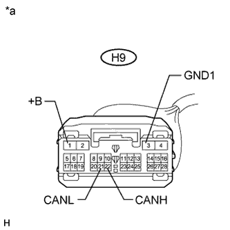 |
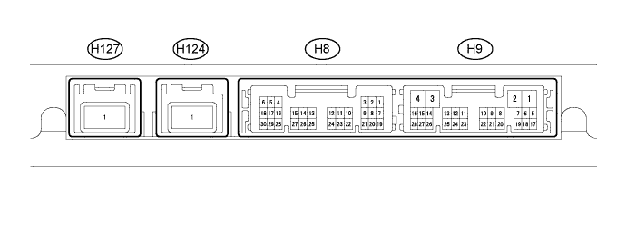
Disconnect the parking assist ECU connector.
| *a | Front view of wire harness connector (to Parking Assist ECU) |
Measure the resistance according to the value(s) in the table below.
| Terminal No. (Symbol) | Wiring Color | Terminal Description | Condition | Specified Condition |
| H9-22 (CANH) - H9-21 (CANL) | P - B | HIGH-level CAN bus line - LOW-level CAN bus line | Power switch off | 54 to 69 Ω |
| H9-22 (CANH) - H9-3 (GND1) | P - W-B | HIGH-level CAN bus line - Ground | Power switch off | 200 Ω or higher |
| H9-21 (CANL) - H9-3 (GND1) | B - W-B | LOW-level CAN bus line - Ground | Power switch off | 200 Ω or higher |
| H9-22 (CANH) - H9-1 (+B) | P - B | HIGH-level CAN bus line - Battery positive (+) | Cable disconnected from negative (-) auxiliary battery terminal | 6 kΩ or higher |
| H9-21 (CANL) - H9-1 (+B) | B - B | LOW-level CAN bus line - Battery positive (+) | Cable disconnected from negative (-) auxiliary battery terminal | 6 kΩ or higher |
| CLEARANCE WARNING ECU ASSEMBLY (w/ LEXUS Parking Assist Sensor System) |
Disconnect the clearance warning ECU assembly connector.
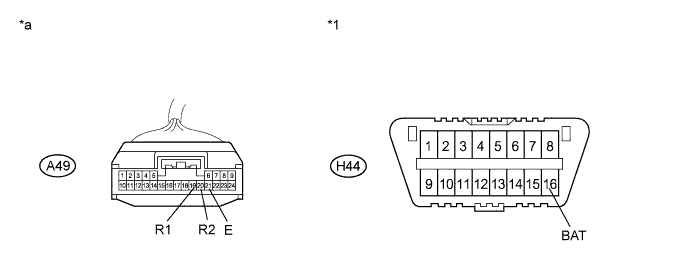
| *1 | DLC3 | - | - |
| *a | Front view of wire harness connector (to Clearance Warning ECU Assembly) | - | - |
Measure the resistance according to the value(s) in the table below.
| Terminal No. (Symbol) | Wiring Color | Terminal Description | Condition | Specified Condition |
| A49-19 (R1) - A49-20 (R2) | Y - BR | HIGH-level CAN bus line - LOW-level CAN bus line | Power switch off | 54 to 69 Ω |
| A49-19 (R1) - A49-21 (E) | Y - W-B | HIGH-level CAN bus line - Ground | Power switch off | 200 Ω or higher |
| A49-20 (R2) - A49-21 (E) | BR - W-B | LOW-level CAN bus line - Ground | Power switch off | 200 Ω or higher |
| A49-19 (R1) - H44-16 (BAT) | Y - R | CAN communication line H - Battery positive (+) | Cable disconnected from negative (-) auxiliary battery terminal | 6 kΩ or higher |
| A49-20 (R2) - H44-16 (BAT) | BR - R | CAN communication line L - Battery positive (+) | Cable disconnected from negative (-) auxiliary battery terminal | 6 kΩ or higher |
