DTC P0343-747 Camshaft Position Sensor "A" Circuit High Input |
| DTC No. | INF Code | DTC Detection Condition | Trouble Area |
| P0343 | 747 | GI signal is not input for 2 sec. or more while the engine is running. |
|
| 1.CHECK DTC OUTPUT (ENGINE AND ECT) |
Connect the intelligent tester to the DLC3.
Turn the power switch on (IG).
Enter the following menus: Powertrain / Engine and ECT/ DTC.
Check if DTCs are output.
| Result | Proceed to |
| SFI system DTCs are not output. | A |
| Any of the following DTCs are output. | B |
| DTC No. | Relevant Diagnosis |
| P0340 | Camshaft Position Sensor Circuit Malfunction |
| P0342 | Camshaft Position Sensor "A" Circuit Low Input (Bank 1 or Single Sensor) |
| P0343 | Camshaft Position Sensor "A" Circuit High Input (Bank 1 or Single Sensor) |
Turn the power switch off.
|
| ||||
| A | |
 |
| 2.CHECK DTC OUTPUT (HYBRID CONTROL) |
Connect the intelligent tester to the DLC3.
Turn the power switch on (IG).
Enter the following menus: Powertrain / Hybrid Control / DTC.
Check if DTCs are output.
| Result | Proceed to |
| None of the following DTCs are output. | A |
| Any of the following DTCs are output. | B |
| DTC No. | Relevant Diagnosis |
| P0A1B (all INF codes)*1 | Drive Motor "A" Control Module |
Turn the power switch off.
|
| ||||
| A | |
|
| 3.CHECK DTC OUTPUT (HYBRID CONTROL) |
Connect the intelligent tester to the DLC3.
Turn the power switch on (IG).
Enter the following menus: Powertrain / Hybrid Control / DTC.
Check if DTCs are output.
| Result | Proceed to |
| P0340-886 is not output. | A |
| P0340-886 is also output. | B |
Turn the power switch off.
|
| ||||
| A | |
|
| 4.CHECK CONNECTOR CONNECTION CONDITION (INVERTER WITH CONVERTER ASSEMBLY CONNECTOR) |
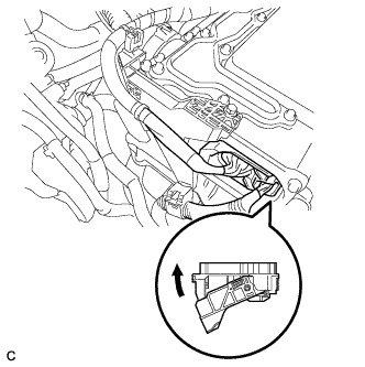 |
Check that the service plug grip is not installed.
Check the connection of the low voltage connector of the inverter with converter assembly.
|
| ||||
| OK | |
|
| 5.CHECK CONNECTOR CONNECTION CONDITION (ECM CONNECTOR) |
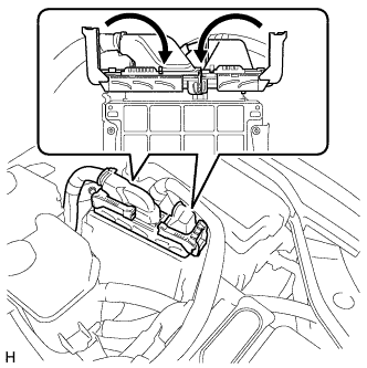 |
Check the connections of the ECM connectors.
|
| ||||
| OK | |
|
| 6.CHECK HARNESS AND CONNECTOR (INVERTER WITH CONVERTER ASSEMBLY - ECM) |
Check that the service plug grip is not installed.
Disconnect the low voltage connector A62 from the inverter with converter assembly.
Disconnect connector D27 from the ECM.
Turn the power switch on (IG).
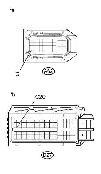 |
Measure the voltage according to the value(s) in the table below.
| Tester Connection | Switch Condition | Specified Condition |
| A62-29 (GI) - Body ground | Power switch on (IG) | Below 1 V |
| *a | Front view of wire harness connector (to Inverter with Converter Assembly) |
| *b | Front view of wire harness connector (to ECM) |
Turn the power switch off.
Measure the resistance according to the value(s) in the table below.
| Tester Connection | Switch Condition | Specified Condition |
| A62-29 (GI) - D27-48 (G2O) | Power switch off | Below 1 Ω |
| Tester Connection | Switch Condition | Specified Condition |
| A62-29 (GI) or D27-48 (G2O) - Body ground and other terminals | Power switch off | 10 kΩ or higher |
Connect the ECM connector.
Connect the inverter with converter assembly connector.
|
| ||||
| OK | ||
 | ||
| ||
| 7.CHECK CONNECTOR CONNECTION CONDITION (ECM CONNECTOR) |
|
Check the connections of the ECM connectors.
|
| ||||
| OK | |
|
| 8.CHECK HARNESS AND CONNECTOR (INVERTER WITH CONVERTER ASSEMBLY - ECM) |
Check that the service plug grip is not installed.
Disconnect the low voltage connector A62 from the inverter with converter assembly.
Disconnect connector D27 from the ECM.
|
Measure the resistance according to the value(s) in the table below.
| Tester Connection | Switch Condition | Specified Condition |
| A62-29 (GI) - D27-48 (G2O) | Power switch off | Below 1 Ω |
| Tester Connection | Switch Condition | Specified Condition |
| A62-29 (GI) or D27-48 (G2O) - Body ground and other terminals | Power switch off | 10 kΩ or higher |
| *a | Front view of wire harness connector (to Inverter with Converter Assembly) |
| *b | Front view of wire harness connector (to ECM) |
Connect the ECM connector.
Connect the inverter with converter assembly connector.
|
| ||||
| OK | |
|
| 9.CHECK HARNESS AND CONNECTOR (ECM - POWER MANAGEMENT CONTROL ECU) |
Disconnect connector D27 from the ECM.
Disconnect connector A19 from the power management control ECU.
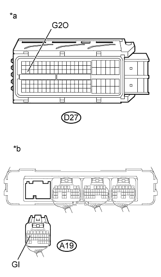 |
Measure the resistance according to the value(s) in the table below.
| Tester Connection | Switch Condition | Specified Condition |
| D27-48 (G2O) - A19-16 (GI) | Power switch off | Below 1 Ω |
| Tester Connection | Switch Condition | Specified Condition |
| D27-48 (G2O) or A19-16 (GI) - Body ground and other terminals | Power switch off | 10 kΩ or higher |
| *a | Front view of wire harness connector (to ECM) |
| *b | Rear view of wire harness connector (to Power Management Control ECU) |
Connect the power management control ECU connector.
Connect the ECM connector.
|
| ||||
| OK | |
|
| 10.CHECK INVERTER WITH CONVERTER ASSEMBLY |
Check that the service plug grip is not installed.
Disconnect the low voltage connector A62 from the inverter with converter assembly.
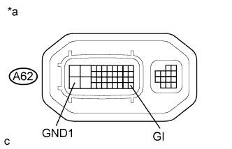 |
Measure the resistance according to the value(s) in the table below.
| Tester Connection | Switch Condition | Specified Condition |
| A62-29 (GI) - A62-28 (GND1) | Power switch off | 10 kΩ or higher |
| *a | Component without harness connected (Inverter with Converter Assembly) |
Connect the inverter with converter assembly connector.
|
| ||||
| OK | |
|
| 11.CHECK POWER MANAGEMENT CONTROL ECU |
Disconnect connectors A19 and H3 from the power management control ECU.
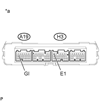 |
Measure the resistance according to the value(s) in the table below.
| Tester Connection | Switch Condition | Specified Condition |
| A19-16 (GI) - H3-6 (E1) | Power switch off | 10 kΩ or higher |
| *a | Component without harness connected (Power Management Control ECU) |
Connect the power management control ECU connector.
|
| ||||
| OK | ||
| ||
| ||


