DTC P0A08-264 DC / DC Converter Status Circuit |
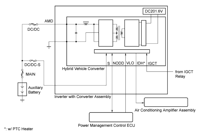
| DTC No. | INF Code | DTC Detection Condition | Trouble Area |
| P0A08 | 264 | DC/DC converter malfunction |
|
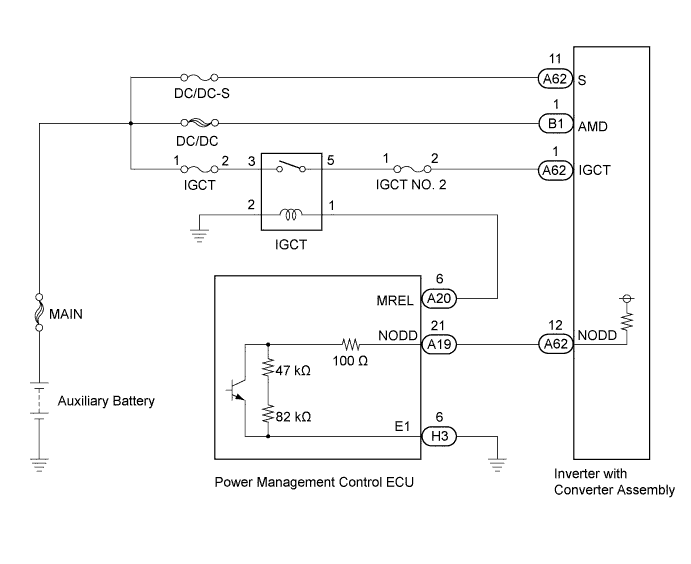
| 1.CHECK DTC OUTPUT (HYBRID CONTROL) |
Connect the intelligent tester to the DLC3.
Turn the power switch on (IG).
Enter the following menus: Powertrain / Hybrid Control / DTC.
Check if DTCs are output.
| Result | Proceed to |
| DTC P0A08-264 only is output. | A |
| Any of the following DTCs are also output. | B |
| DTC No. | Relevant Diagnosis |
| P0A93-346 | Inverter Cooling System Performance |
| P0A94-547, 548, 549 | DC / DC Converter Performance |
| P0AA6-526, 613 | Hybrid Battery Voltage System Isolation Fault |
| P0ADB-227 | Hybrid Battery Positive Contactor Control Circuit Low |
| P0ADF-229 | Hybrid Battery Negative Contactor Control Circuit Low |
| P0AE6-225 | Hybrid Battery Precharge Contactor Control Circuit Low |
| P0C73-776 | Motor Electronics Coolant Pump "A" Control Performance |
| P3004-131, 803 | Power Cable Malfunction |
| P314A-828 | Inverter Coolant Pump Speed Signal |
Turn the power switch off.
|
| ||||
| A | |
 |
| 2.CHECK FUSE (IGCT NO. 2) |
Disconnect the cable from the negative auxiliary battery terminal.
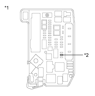
Remove the IGCT No. 2 fuse from the engine room junction block assembly.
 |
Measure the resistance according to the value(s) in the table below.
| Tester Connection | Condition | Specified Condition |
| IGCT No. 2 fuse terminals | Always | Below 1 Ω |
| *1 | Engine Room Junction Block Assembly |
| *2 | IGCT No. 2 Fuse |
Install the IGCT No. 2 fuse.
|
| ||||
| OK | |
|
| 3.CHECK FUSE (DC/DC-S) |
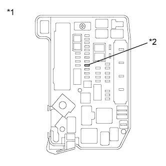 |
Remove the DC/DC-S fuse from the engine room junction block assembly.
Measure the resistance according to the value(s) in the table below.
| Tester Connection | Condition | Specified Condition |
| DC/DC-S fuse terminals | Always | Below 1 Ω |
| *1 | Engine Room Junction Block Assembly |
| *2 | DC/DC-S Fuse |
Install the DC/DC-S fuse.
|
| ||||
| OK | |
|
| 4.CHECK FUSE (IGCT) |
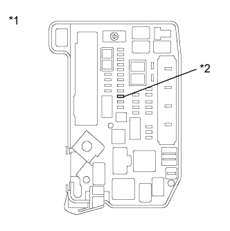 |
Remove the IGCT fuse from the engine room junction block assembly.
Measure the resistance according to the value(s) in the table below.
| Tester Connection | Condition | Specified Condition |
| IGCT fuse terminals | Always | Below 1 Ω |
| *1 | Engine Room Junction Block Assembly |
| *2 | IGCT Fuse |
Install the IGCT fuse.
|
| ||||
| OK | |
|
| 5.CHECK FUSIBLE LINK (DC/DC) |
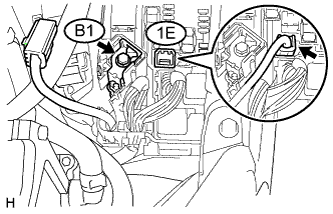 |
Disconnect connector 1E from the engine room junction block assembly.
Measure the resistance according to the value(s) in the table below.
| Tester Connection | Condition | Specified Condition |
| 1E-1 - B1-1 (AMD) | Always | Below 1 Ω |
Check the fusible links (DC/DC) in the engine room junction block assembly for improper installation.
Connect the engine room junction block assembly connector.
|
| ||||
| OK | |
|
| 6.CHECK CONNECTOR CONNECTION CONDITION (POWER MANAGEMENT CONTROL ECU CONNECTOR) |
Check the connections of the power management control ECU connectors.
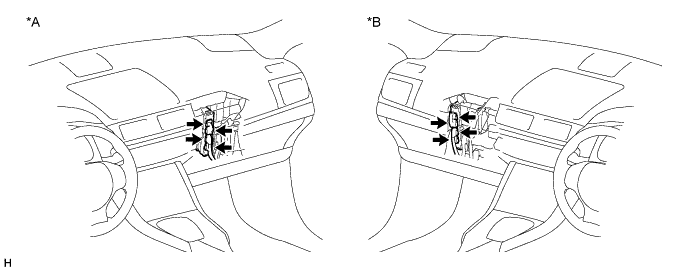
| *A | for LHD | *B | for RHD |
|
| ||||
| OK | |
|
| 7.CHECK CONNECTOR CONNECTION CONDITION (INVERTER WITH CONVERTER ASSEMBLY CONNECTOR) |
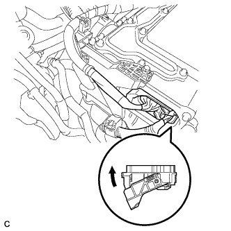 |
Check that the service plug grip is not installed.
Check the connection of the low voltage connector of the inverter with converter assembly.
|
| ||||
| OK | |
|
| 8.CHECK CABLE AND WIRE HARNESS |
Check that the service plug grip is not installed.
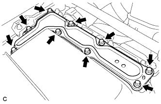 |
Remove the inverter cover from the inverter with converter assembly.
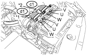 |
Using a megohmmeter set to 500 V, measure the insulation resistance according to the value(s) in the table below.
| Tester Connection | Switch Condition | Specified Condition |
| d1-1 (W) - Body ground and shield ground | Power switch off | 1 MΩ or higher |
| d1-2 (U) - Body ground and shield ground | Power switch off | 1 MΩ or higher |
| d1-3 (V) - Body ground and shield ground | Power switch off | 1 MΩ or higher |
| c1-1 (W) - Body ground and shield ground | Power switch off | 1 MΩ or higher |
| c1-2 (U) - Body ground and shield ground | Power switch off | 1 MΩ or higher |
| c1-3 (V) - Body ground and shield ground | Power switch off | 1 MΩ or higher |
| *1 | Three-phase AC Cable for MG1 |
| *2 | Three-phase AC Cable for MG2 |
Install the inverter cover to the inverter with converter assembly.
|
| ||||
| OK | |
|
| 9.CHECK ENGINE ROOM JUNCTION BLOCK ASSEMBLY (AMD TERMINAL CONNECTION CONDITION) |
Check that the service plug grip is not installed.
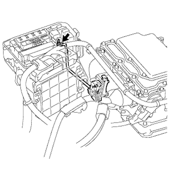 |
Check that the bolt for the AMD terminal is tightened to the specified torque, the AMD terminal is connected securely, and there is no contact problem.
| Result | Proceed to | |
| There are no arc marks. | The terminal is connected securely and there is no contact problem. | A |
| There are no arc marks. | The terminal is not connected securely and there is a contact problem. | B |
| There are arc marks. | - | C |
|
| ||||
|
| ||||
| A | |
|
| 10.CHECK TERMINAL VOLTAGE (AMD TERMINAL VOLTAGE) |
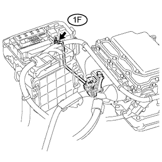 |
Measure the voltage according to the value(s) in the table below.
| Tester Connection | Switch Condition | Specified Condition |
| 1F-1 - Body ground | Power switch off | 11 to 14 V |
|
| ||||
| OK | |
|
| 11.CHECK HARNESS AND CONNECTOR (ENGINE ROOM JUNCTION BLOCK - INVERTER WITH CONVERTER) |
Check that the service plug grip is not installed.
Disconnect connector A62 from the inverter with converter assembly.
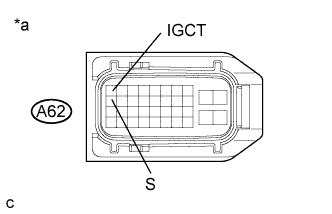 |
Measure the voltage according to the value(s) in the table below.
| Tester Connection | Switch Condition | Specified Condition |
| A62-11 (S) - Body ground | Always | 11 to 14 V |
| *a | Front view of wire harness connector (to Inverter with Converter Assembly) |
Turn the power switch on (IG).
Measure the voltage according to the value(s) in the table below.
| Tester Connection | Switch Condition | Specified Condition |
| A62-1 (IGCT) - Body ground | Power switch on (IG) | 11 to 14 V |
Turn the power switch off.
Connect the inverter with converter assembly connector.
|
| ||||
| OK | |
|
| 12.CHECK POWER MANAGEMENT CONTROL ECU |
Check that the service plug grip is not installed.
Disconnect connector A62 from the inverter with converter assembly.
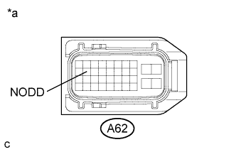 |
Measure the resistance according to the value(s) in the table below.
| Tester Connection | Switch Condition | Specified Condition |
| A62-12 (NODD) - Body ground | Power switch off | 120 to 140 kΩ |
| *a | Front view of wire harness connector (to Inverter with Converter Assembly) |
Connect the inverter with converter assembly connector.
|
| ||||
| OK | |
|
| 13.CHECK DC/DC CONVERTER FUNCTION |
Connect the AC/DC 400 A probe to the positive auxiliary battery line.
Install the service plug grip.
Turn the power switch on (READY) and leave the vehicle as it is until the electric current flowing into the auxiliary battery becomes 10 A or less.
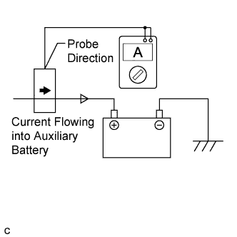 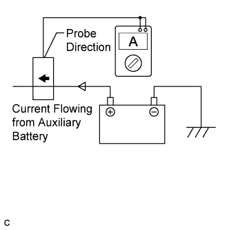 |
Measure the current flowing from the auxiliary battery with the power switch on (READY), the headlight position switch and blower motor switch in the HI position, and the rear window defogger turned on.
| Item | Switch Condition | Specified Condition |
| Current flowing from auxiliary battery | Power switch on (READY) (The headlight position switch and blower motor switch are in the HI position, and the rear window defogger is turned on.) | 0 A or less (no current from auxiliary battery) |
Measure the voltage according to the value(s) in the table below.
| Tester Connection | Switch Condition | Specified Condition |
| Auxiliary battery voltage | Power switch on (READY) (The headlight position switch and blower motor switch are in the HI position, and the rear window defogger is turned on.) | 13 to 15 V |
Turn the power switch off.
|
| ||||
| OK | |
|
| 14.CHECK QUANTITY OF HV COOLANT |
Check the coolant level in the inverter reserve tank.
Check for coolant leaks.
| Result | Proceed to |
| Coolant leaks are not evident. A sufficient amount of coolant remains in the inverter reserve tank. | A |
| Coolant leaks are not evident. No coolant remains in the inverter reserve tank. | B |
| Coolant leaks are evident. | C |
|
| ||||
|
| ||||
| A | |
|
| 15.CHECK COOLANT HOSE |
Check if the hoses of the cooling system are kinked or clogged.
|
| ||||
| OK | |
|
| 16.PERFORM ACTIVE TEST USING INTELLIGENT TESTER (CONTROL THE ELECTRIC COOLING FAN) |
Connect the intelligent tester to the DLC3.
Turn the power switch on (IG).
Enter the following menus: Powertrain / Engine and ECT / Active Test / Control the Electric Cooling Fan.
Perform the "Control the Electric Cooling Fan" Active Test.
Turn the power switch off.
|
| ||||
| OK | |
|
| 17.CHECK HV COOLANT (CHECK FOR CONDITIONS THAT MAY HAVE CAUSED FREEZING) |
Connect the intelligent tester to the DLC3.
Turn the power switch on (IG).
Read the freeze frame data Ambient Temperature using the intelligent tester.
Check if the freeze frame data Ambient Temperature is below freezing.
| Result | Proceed to |
| Ambient Temperature value is above freezing temperature of the HV coolant | A |
| Ambient Temperature value is below freezing temperature of the HV coolant | B |
Turn the power switch off.
|
| ||||
| A | ||
 | ||
| ||
| 18.CHECK HYBRID VEHICLE TRANSAXLE ASSEMBLY (MG1) |
Check that the service plug grip is not installed.
|
Remove the inverter cover from the inverter with converter assembly.
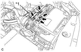 |
Disconnect the three-phase AC cables for MG1 from the inverter with converter assembly.
| *1 | Three-phase AC Cables for MG1 |
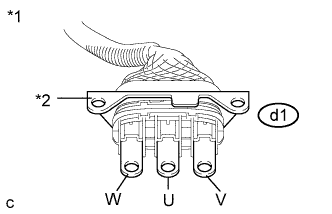 |
Using a megohmmeter set to 500 V, measure the insulation resistance according to the value(s) in the table below.
| Tester Connection | Switch Condition | Specified Condition |
| d1-1 (W) - Body ground and shield ground | Power switch off | 100 MΩ or higher |
| d1-2 (U) - Body ground and shield ground | Power switch off | 100 MΩ or higher |
| d1-3 (V) - Body ground and shield ground | Power switch off | 100 MΩ or higher |
| *1 | Three-phase AC Cables for MG1 |
| *2 | Shield Ground |
Connect the three-phase AC cables for MG1 to the inverter with converter assembly.
Install the inverter cover to the inverter with converter assembly.
|
| ||||
| OK | |
|
| 19.CHECK HYBRID VEHICLE TRANSAXLE ASSEMBLY (MG2) |
Check that the service plug grip is not installed.
|
Remove the inverter cover from the inverter with converter assembly.
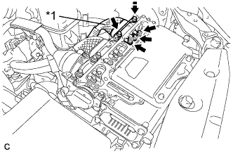 |
Disconnect the three-phase AC cables for MG2 from the inverter with converter assembly.
| *1 | Three-phase AC Cables for MG2 |
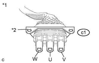 |
Using a megohmmeter set to 500 V, measure the insulation resistance according to the value(s) in the table below.
| Tester Connection | Switch Condition | Specified Condition |
| c1-1 (W) - Body ground and shield ground | Power switch off | 100 MΩ or higher |
| c1-2 (U) - Body ground and shield ground | Power switch off | 100 MΩ or higher |
| c1-3 (V) - Body ground and shield ground | Power switch off | 100 MΩ or higher |
| *1 | Three-phase AC Cables for MG2 |
| *2 | Shield Ground |
Connect the three-phase AC cables for MG2 to the inverter with converter assembly.
Install the inverter cover to the inverter with converter assembly.
|
| ||||
| OK | ||
| ||
| ||
| 20.INSPECT POWER MANAGEMENT CONTROL ECU |
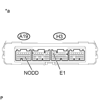 |
Disconnect all the connectors from the power management control ECU.
Measure the resistance according to the value(s) in the table below.
| Tester Connection | Switch Condition | Specified Condition |
| A19-21 (NODD) - H3-6 (E1) | Power switch off | 120 to 140 kΩ |
| *a | Component without harness connected (Power Management Control ECU) |
Connect the power management control ECU connectors.
|
| ||||
| OK | ||
| ||
| ||
| 21.REPLACE HV COOLANT |
Replace the HV coolant with coolant having an appropriate concentration (appropriate freeze point) for the vehicle usage conditions (Click here).
| NEXT | |
|
| 22.CHECK INVERTER WATER PUMP ASSEMBLY |
Perform a road test and check that DTCs are not stored.
|
| ||||
| OK | ||
| ||
| ||
| 23.CHECK HYBRID VEHICLE TRANSAXLE ASSEMBLY (GENERATOR CABLE CONNECTION CONDITION) |
Check that the service plug grip is not installed.
Remove the inverter with converter assembly.
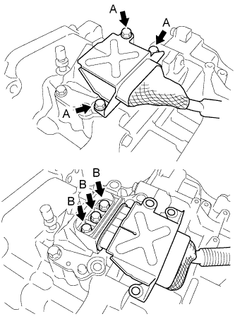 |
Check that the bolts for the generator cable are tightened to the specified torque, the generator cable is connected securely, and there are no contact problems.
Disconnect the generator cable from the hybrid transaxle assembly.
Check for arc marks at the bolts for the generator cable.
| Result | Proceed to | |
| The terminals are connected securely and there are no contact problems. | There are no arc marks. | A |
| The terminals are not connected securely and there is a contact problem. | There are arc marks. | B |
| The terminals are not connected securely and there is a contact problem. | There are no arc marks. | C |
| The terminals are connected securely and there are no contact problems. | There are arc marks. | B |
Connect the generator cable to the hybrid transaxle assembly.
Install the inverter with converter assembly.
|
| ||||
|
| ||||
| A | |
|
| 24.CHECK GENERATOR CABLE |
Check that the service plug grip is not installed.
Remove the generator cable.
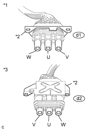 |
Using a megohmmeter set to 500 V, measure the resistance according to the value(s) in the table below.
| Tester Connection | Switch Condition | Specified Condition |
| d1-1 (W) - Body ground and shield ground | Power switch off | 100 MΩ or higher |
| d1-2 (U) - Body ground and shield ground | Power switch off | 100 MΩ or higher |
| d1-3 (V) - Body ground and shield ground | Power switch off | 100 MΩ or higher |
| *1 | Generator Cable (Inverter with Converter Assembly Side) |
| *2 | Shielded Ground |
| *3 | Generator Cable (Hybrid Vehicle Transaxle Assembly Side) |
Measure the resistance according to the value(s) in the table below.
| Tester Connection | Switch Condition | Specified Condition |
| d1-1 (W) - d2-3 (W) | Power switch off | Below 1 Ω |
| d1-2 (U) - d2-2 (U) | Power switch off | Below 1 Ω |
| d1-3 (V) - d2-1 (V) | Power switch off | Below 1 Ω |
| d1-1 (W) - d2-2 (U) | Power switch off | 100 MΩ or higher |
| d1-2 (U) - d2-1 (V) | Power switch off | 100 MΩ or higher |
| d1-3 (V) - d2-3 (W) | Power switch off | 100 MΩ or higher |
Install the generator cable.
|
| ||||
| OK | ||
| ||
| ||
| 25.CHECK HYBRID VEHICLE TRANSAXLE ASSEMBLY (MOTOR CABLE CONNECTION CONDITION) |
Check that the service plug grip is not installed.
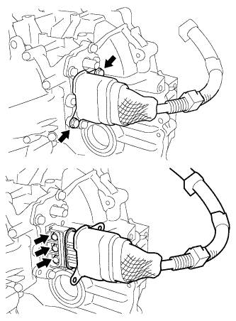 |
Check that the bolts for the motor cable are tightened to the specified torque, the motor cable is connected securely, and there are no contact problems.
Disconnect the motor cable from the hybrid transaxle assembly.
Check for arc marks at the bolts for the motor cable.
| Result | Proceed to | |
| The terminals are connected securely and there are no contact problems. | There are no arc marks. | A |
| The terminals are not connected securely and there is a contact problem. | There are arc marks. | B |
| The terminals are not connected securely and there is a contact problem. | There are no arc marks. | C |
| The terminals are connected securely and there are no contact problems. | There are arc marks. | B |
Connect the motor cable to the hybrid transaxle assembly.
|
| ||||
|
| ||||
| A | |
|
| 26.CHECK MOTOR CABLE |
Check that the service plug grip is not installed.
Remove the motor cable.
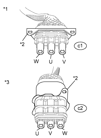 |
Using a megohmmeter set to 500 V, measure the resistance according to the value(s) in the table below.
| Tester Connection | Switch Condition | Specified Condition |
| c1-1 (W) - Body ground and shield ground | Power switch off | 100 MΩ or higher |
| c1-2 (U) - Body ground and shield ground | Power switch off | 100 MΩ or higher |
| c1-3 (V) - Body ground and shield ground | Power switch off | 100 MΩ or higher |
| *1 | Motor Cable (Inverter with Converter Assembly Side) |
| *2 | Shielded Ground |
| *3 | Motor Cable (Hybrid Vehicle Transaxle Assembly Side) |
Measure the resistance according to the value(s) in the table below.
| Tester Connection | Switch Condition | Specified Condition |
| c1-1 (W) - c2-1 (W) | Power switch off | Below 1 Ω |
| c1-2 (U) - c2-3 (U) | Power switch off | Below 1 Ω |
| c1-3 (V) - c2-2 (V) | Power switch off | Below 1 Ω |
| c1-1 (W) - c2-3 (U) | Power switch off | 100 MΩ or higher |
| c1-2 (U) - c2-2 (V) | Power switch off | 100 MΩ or higher |
| c1-3 (V) - c2-1 (W) | Power switch off | 100 MΩ or higher |
Install the motor cable.
|
| ||||
| OK | ||
| ||
| ||
| 27.CHECK HARNESS AND CONNECTOR (INVERTER WITH CONVERTER ASSEMBLY - IGCT NO. 2 FUSE) |
Check that the service plug grip is not installed.
Disconnect connector A62 from the inverter with converter assembly.
|
Remove the IGCT No. 2 fuse from the engine room junction block assembly.
| *1 | Engine Room Junction Block Assembly |
| *2 | IGCT No. 2 Fuse |
Measure the resistance according to the value(s) in the table below.
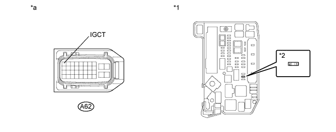
| *1 | Engine Room Junction Block Assembly | *2 | IGCT No. 2 Fuse |
| *a | Front view of wire harness connector (to Inverter with Converter Assembly) | - | - |
| Tester Connection | Switch Condition | Specified Condition |
| A62-1 (IGCT) or 2 (IGCT No. 2 fuse) - Body ground and other terminals | Power switch off | 10 kΩ or higher |
Install the IGCT No. 2 fuse.
Connect the inverter with converter assembly connector.
|
| ||||
| OK | |
|
| 28.REPLACE INVERTER WITH CONVERTER ASSEMBLY |
Replace the inverter with converter assembly (Click here).
| NEXT | ||
| ||
| ||
| 29.CHECK HARNESS AND CONNECTOR (INVERTER WITH CONVERTER ASSEMBLY - DC/DC-S FUSE) |
Disconnect connector A62 from the inverter with converter assembly.
|
Remove the DC/DC-S fuse from the engine room junction block assembly.
| *1 | Engine Room Junction Block Assembly |
| *2 | DC/DC-S Fuse |
Measure the resistance according to the value(s) in the table below.
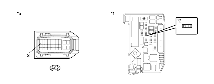
| *1 | Engine Room Junction Block Assembly | *2 | DC/DC-S Fuse |
| *a | Front view of wire harness connector (to Inverter with Converter Assembly) | - | - |
| Tester Connection | Switch Condition | Specified Condition |
| A62-11 (S) or 2 (DC/DC-S fuse) - Body ground and other terminals | Power switch off | 10 kΩ or higher |
Install the DC/DC-S fuse.
Connect the inverter with converter assembly connector.
|
| ||||
| OK | |
|
| 30.REPLACE INVERTER WITH CONVERTER ASSEMBLY |
Replace the inverter with converter assembly (Click here).
| NEXT | ||
| ||
| ||
| 31.CHECK ENGINE ROOM JUNCTION BLOCK ASSEMBLY (IGCT RELAY, IGCT FUSE, IGCT NO. 2 FUSE) |
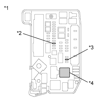 |
Remove the IGCT relay, IGCT fuse and IGCT No. 2 fuse from the engine room junction block assembly.
| *1 | Engine Room Junction Block Assembly |
| *2 | IGCT Fuse |
| *3 | IGCT No. 2 Fuse |
| *4 | IGCT Relay |
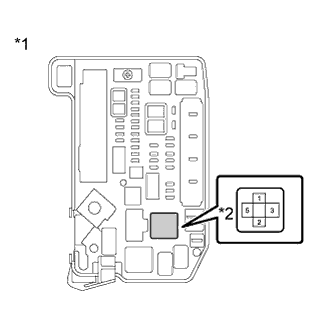 |
Measure the resistance according to the value(s) in the table below.
| Tester Connection | Condition | Specified Condition |
| 3 (IGCT relay block) - Body ground and other terminals | Always | 10 kΩ or higher |
| 5 (IGCT relay block) - Body ground and other terminals | Always | 10 kΩ or higher |
| *1 | Engine Room Junction Block Assembly |
| *2 | IGCT Relay |
Install the IGCT relay, IGCT fuse and IGCT No. 2 fuse.
|
| ||||
| OK | ||
| ||
| ||
| 32.REPAIR OR REPLACE HARNESS OR CONNECTOR |
| NEXT | ||
| ||
| ||
| 33.REPAIR OR REPLACE HARNESS OR CONNECTOR |
| NEXT | ||
| ||
| ||
| 34.REPAIR OR REPLACE ENGINE ROOM JUNCTION BLOCK ASSEMBLY |
| NEXT | ||
| ||
| ||


