DTC    C1241/41    Low Battery Positive Voltage

DTC    C1242/42    Open in IG1 / IG2 Power Source Circuit

for Preparation Click here


DESCRIPTION

If a malfunction is detected in the power supply circuit, the skid control ECU power source voltage drops, or there is insufficient voltage to operate the ABS main relay, the skid control ECU will store these DTCs.
These DTCs may also be stored if the auxiliary battery voltage drops below 9.5 V.

HINT:
DTC C1256/56 (Accumulator Low Pressure) may also be memorized if there is a drop in power source voltage.


DTC Code
INF Code
DTC Detection Condition
Trouble Area
C1241/41
101
Any of the following conditions when the BS terminal voltage is 9.3 V or less:
  1. Vehicle not decelerated (brake pedal is not depressed) for 3 seconds or more.
  2. While depressing the brake pedal, linear solenoid current does not satisfy 1.34 A.
  3. Vehicle decelerated (brake pedal is depressed) for 0.06 seconds.
  1. Improperly connected connector, deformation or corrosion of terminals
  2. Auxiliary battery
  3. Hybrid control system (Charging circuit)
  4. Brake booster with master cylinder (Skid control ECU)

102
Either of the following conditions when the ECU internal voltage is 6.3 V or less:
  1. When main relay ON is requested, voltage of the relay connection does not exceed 3.5 V for 0.22 seconds or more.
  2. Sensor supply voltage is 4.75 V or less, or 5.25 V or more for 0.06 seconds.
  3. Accumulator pressure sensor output voltage is 4.54 V or less, or 5.46 V or more for 0.06 seconds.


551
When driving at 3 km/h (1.9 mph) or more, IG1 terminal voltage is 9.5 V or less, or VM1 voltage is 8.6 V or less for 10 seconds or more.


552
When VM1 voltage is 8.6 V or less, sensor supply voltage is low for 60 seconds or more.


553
VM1 voltage is 16.6 V or more for 0.8 seconds.

C1242/42
111
Voltage is not applied to the IG1 terminal (less than 3.5 V), and applied to the IG2 terminal (9.5 V or more) for 4 seconds or more.
  1. Open or short in IG1 circuit
  2. Improperly connected connector, deformation or corrosion of terminals
  3. Entry and start system (IG start circuit)
  4. Auxiliary battery
  5. Hybrid control system (Charging circuit)
  6. Brake booster with master cylinder (Skid control ECU)

112
Voltage is not applied to the IG2 terminal (less than 3.5 V), and applied to the IG1 terminal (9.5 V or more) for 4 seconds or more.
  1. Open or short in IG2 circuit
  2. Improperly connected connector, deformation or corrosion of terminals
  3. Entry and start system (IG start circuit)
  4. Auxiliary battery
  5. Hybrid control system (Charging circuit)
  6. Brake booster with master cylinder (Skid control ECU)

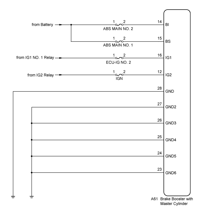
WIRING DIAGRAM


C209669E03


INSPECTION PROCEDURE

NOTICE:
When replacing the brake booster with master cylinder (skid control ECU), perform initialization and calibration of the linear solenoid valve (Click here).

1.CHECK ENTRY AND START SYSTEM (for Start Function)
  1. Check if the entry and start system (for start function) DTC is output (Click here).

    Result:

    Result
    Proceed to
    DTC is not output
    A
    DTC is output
    B


B
INSPECT ENTRY AND START SYSTEM (for Start Function) (Click here)
A


2.CHECK HYBRID CONTROL SYSTEM
  1. Check if the hybrid control system DTC is output (Click here).

    Result:

    Result
    Proceed to
    DTC is not output
    A
    DTC is output
    B


B
INSPECT HYBRID CONTROL SYSTEM (Click here)
A


3.CHECK DTC
  1. Check that no main relay DTC is output (Click here).

    Result:

    Result
    Proceed to
    Main relay malfunction DTC is not output
    A
    Main relay malfunction DTC is output
    B


B
REPAIR CIRCUITS INDICATED BY OUTPUT DTCS (Click here)
A


4.CHECK AUXILIARY BATTERY
  1. Check the auxiliary battery voltage.

    Standard Voltage:
    11 to 14 V


NG
CHARGE OR REPLACE AUXILIARY BATTERY
OK


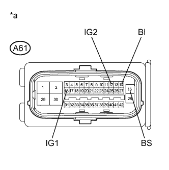
5.INSPECT SKID CONTROL ECU (POWER SOURCE TERMINAL)


    C209401E59
  1. Make sure that there is no looseness at the locking part and the connecting part of the connector.

  1. Disconnect the skid control ECU connector.

  1. Measure the voltage according to the value(s) in the table below.

    Standard Voltage:
    Tester Connection
    Condition
    Specified Condition
    A61-14 (BI) - Body ground
    Always
    11 to 14 V
    A61-15 (BS) - Body ground
    Always
    11 to 14 V
    A61-16 (IG1) - Body ground
    Power switch on (IG)
    11 to 14 V
    A61-12 (IG2) - Body ground
    Power switch on (IG)
    11 to 14 V

    Text in Illustration 
    *a
    Front view of wire harness connector
    (to Skid Control ECU)


NG
REPAIR OR REPLACE HARNESS OR CONNECTOR (POWER SOURCE CIRCUIT)
OK


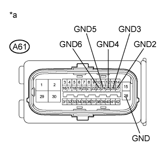
6.INSPECT SKID CONTROL ECU (GND TERMINAL)


    C209401E60
  1. Turn the power switch off.

  1. Measure the resistance according to the value(s) in the table below.

    Standard Resistance:
    Tester Connection
    Condition
    Specified Condition
    A61-28 (GND) - Body ground
    Always
    Below 1 Ω
    A61-27 (GND2) - Body ground
    Always
    Below 1 Ω
    A61-26 (GND3) - Body ground
    Always
    Below 1 Ω
    A61-25 (GND4) - Body ground
    Always
    Below 1 Ω
    A61-24 (GND5) - Body ground
    Always
    Below 1 Ω
    A61-23 (GND6) - Body ground
    Always
    Below 1 Ω

    Text in Illustration 
    *a
    Front view of wire harness connector
    (to Skid Control ECU)


NG
REPAIR OR REPLACE HARNESS OR CONNECTOR (GND CIRCUIT)
OK


7.RECONFIRM DTC
  1. Reconnect the skid control ECU connector.

  1. Clear the DTCs (Click here).

  1. Turn the power switch on (READY).

  1. Perform a road test.

  1. Check if the same DTC is recorded (Click here).

    Result:

    Result
    Proceed to
    DTCs (C1241/41 and C1242/42) are not output
    A
    DTCs (C1241/41 and/or C1242/42) are output (for LHD)
    B
    DTCs (C1241/41 and/or C1242/42) are output (for RHD)
    C

    HINT:
    If troubleshooting has been carried out according to Problem Symptoms Table, refer back to the table and proceed to the next step (Click here).


B
REPLACE BRAKE BOOSTER WITH MASTER CYLINDER (Click here)

C
REPLACE BRAKE BOOSTER WITH MASTER CYLINDER (Click here)
A

CHECK FOR INTERMITTENT PROBLEMS (Click here)