HOOD LOCK CONTROL CABLE ASSEMBLY > INSTALLATION |
| 1. INSTALL HOOD LOCK CONTROL CABLE ASSEMBLY (for LHD) |
Pass the hood lock control cable assembly into the engine compartment.
Pass the cable through the upper radiator support.
Engage each clamp.
| 2. INSTALL HOOD LOCK CONTROL CABLE ASSEMBLY (for RHD) |
Pass the hood lock control cable assembly into the engine compartment.
Pass the cable through the upper radiator support.
Engage each clamp.
| 3. INSTALL HOOD LOCK ASSEMBLY (w/o Engine Hood Courtesy Switch) |
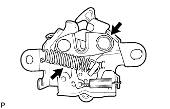 |
Apply MP grease to the sliding areas of the lock.
Connect the hood lock control cable.
Install the hood lock assembly with the 2 bolts and hood lock bolt.
Install a new hood lock nut cap.
| 4. INSTALL HOOD LOCK ASSEMBLY (w/ Engine Hood Courtesy Switch) |
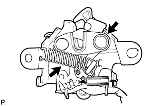 |
Apply MP grease to the sliding areas of the lock.
Connect the hood lock control cable.
Install the hood lock assembly with the 2 bolts and hood lock bolt.
Install a new hood lock nut cap.
Engage the clamp.
Connect the connector.
| 5. INSTALL HOOD LOCK CONTROL LEVER SUB-ASSEMBLY |
Connect the hood lock control cable assembly and install the hood lock control lever sub-assembly.
| 6. CONNECT HOOD LOCK CONTROL LEVER SUB-ASSEMBLY |
Engage the 2 guides and claw to connect the hood lock control lever sub-assembly.
| 7. INSTALL NO. 1 INSTRUMENT PANEL UNDER COVER SUB-ASSEMBLY (for LHD) |
Connect each connector.
Engage the clamp.
Engage the clip.
Install the No. 1 instrument panel under cover sub-assembly with the 2 screws <E>.
| 8. INSTALL COWL SIDE TRIM SUB-ASSEMBLY LH (for LHD) |
Engage the claw and clip.
Install the cowl side trim sub-assembly LH with the clip.
| 9. INSTALL FRONT DOOR SCUFF PLATE LH (for LHD) |
Engage the 4 claws, 2 guides and 4 clips to install the front door scuff plate LH.
| 10. INSTALL NO. 1 INSTRUMENT PANEL UNDER COVER SUB-ASSEMBLY (for RHD) |
Connect each connector.
Engage the clamp.
Engage the 2 clips.
Install the No. 1 instrument panel under cover sub-assembly with the screw <E>.
| 11. INSTALL COWL SIDE TRIM SUB-ASSEMBLY RH (for RHD) |
| 12. INSTALL FRONT DOOR SCUFF PLATE RH (for RHD) |
| 13. INSTALL FRONT FENDER LINER LH (for LHD) |
| 14. INSTALL FRONT WHEEL LH (for LHD) |
| 15. INSTALL FRONT FENDER LINER RH (for RHD) |
Install the front fender liner RH with the 6 clips and 6 screws.
Install the bolt.
Install 2 new grommets.
Using a 4 mm hexagon wrench, install the 3 screws.
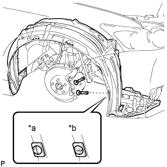 |
Install the 2 pin hold clips as shown in the illustration.
| *a | Correct |
| *b | Incorrect |
| 16. INSTALL FRONT WHEEL RH (for RHD) |
| 17. INSTALL MILLIMETER WAVE RADAR SENSOR ASSEMBLY (w/ Dynamic Radar Cruise Control System) |
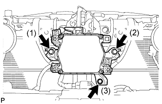 |
Tighten the 3 bolts on the millimeter wave radar sensor assembly.
Connect the connector.
| 18. INSTALL FRONT BUMPER ASSEMBLY |
| 19. ADJUST MILLIMETER WAVE RADAR SENSOR ASSEMBLY (w/ Dynamic Radar Cruise Control System) |
| 20. INSPECT HOOD SUB-ASSEMBLY |
Check that the clearance measurements of areas *a through *e are within each standard range.
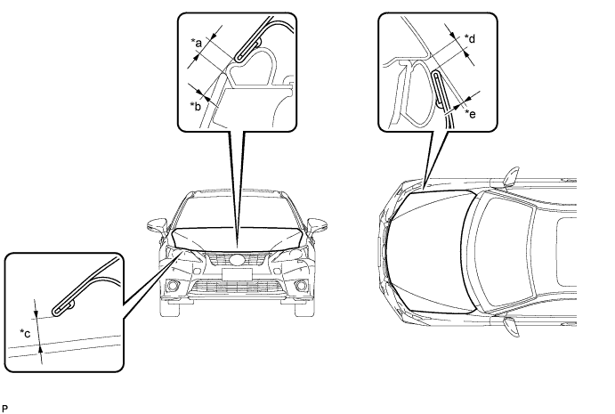
| Area | Measurement | Area | Measurement |
| *a | 3.3 to 7.3 mm (0.130 to 0.287 in.) | *b | -1.5 to 1.5 mm (-0.0591 to 0.0591 in.) |
| *c | 5.65 to 9.65 mm (0.222 to 0.380 in.) | *d | 2.5 to 5.5 mm (0.0984 to 0.217 in.) |
| *e | -0.6 to 2.4 mm (-0.0236 to 0.0945 in.) | - | - |
| 21. ADJUST HOOD SUB-ASSEMBLY |
