DTC P0A38-257 Generator Temperature Sensor Circuit Low |
DTC P0A39-259 Generator Temperature Sensor Circuit High |
| DTC No. | INF Code | DTC Detection Condition | Trouble Area |
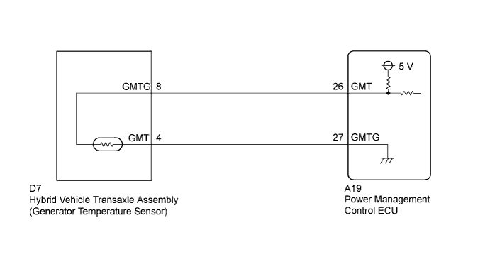
| P0A38 | 257 | Short or short to GND in the generator temperature sensor circuit |
|
| P0A39 | 259 | Open or short to +B in the generator temperature sensor circuit |
| Displayed Temperature | Malfunction |
| -40°C (-40°F) | Open circuit or short to +B |
| 215°C (419°F) | Short circuit or short to GND |
| 1.CHECK CONNECTOR CONNECTION CONDITION (POWER MANAGEMENT CONTROL ECU CONNECTOR) |
Check the connections of the power management control ECU connectors.
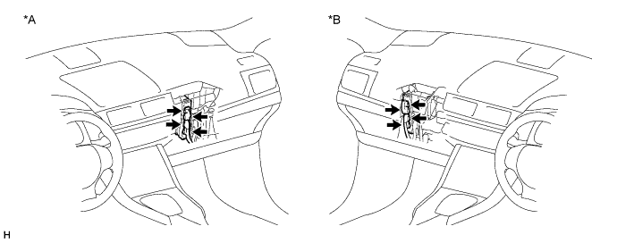
| *A | for LHD | *B | for RHD |
|
| ||||
| OK | |
 |
| 2.READ VALUE USING INTELLIGENT TESTER (MOTOR TEMP NO2) |
Connect the intelligent tester to the DLC3.
Turn the power switch on (IG).
Enter the following menus: Powertrain / Hybrid Control / Data List / Motor Temp No2.
Read the Data List.
| Result | Proceed to |
| -40°C (-40°F) | A |
| 215°C (419°F) | B |
| Same as actual temperature | C |
Turn the power switch off.
|
| ||||
|
| ||||
| A | |
|
| 3.READ VALUE USING INTELLIGENT TESTER (CHECK FOR OPEN) |
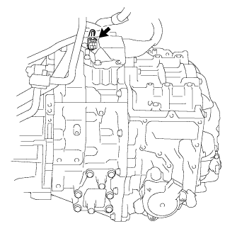 |
Disconnect the generator temperature sensor connector.
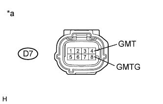 |
Connect terminals 4 (GMT) and 8 (GMTG) of vehicle side connector D7 of the generator temperature sensor.
Connect the intelligent tester to the DLC3.
Turn the power switch on (IG).
Enter the following menus: Powertrain / Hybrid Control / Data List / Motor Temp No2.
Read the Data List.
| Tester Display | Condition | Specified Condition |
| Motor Temp No2 | Terminals GMT and GMTG connected. Power switch on (IG) | 215°C (419°F) |
| *a | Front view of wire harness connector (to Generator Temperature Sensor) |
Turn the power switch off.
Connect the generator temperature sensor connector.
|
| ||||
| OK | ||
 | ||
| ||
| 4.CHECK HARNESS AND CONNECTOR (POWER MANAGEMENT CONTROL ECU - GENERATOR TEMPERATURE SENSOR) |
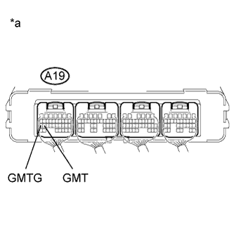 |
Connect terminals 26 (GMT) and 27 (GMTG) of connector A19 of the power management control ECU.
Connect the intelligent tester to the DLC3.
Turn the power switch on (IG).
Enter the following menus: Powertrain / Hybrid Control / Data List / Motor Temp No2.
Read the Data List.
| Tester Display | Condition | Specified Condition |
| Motor Temp No2 | Terminals GMT and GMTG connected. Power switch on (IG) | 215°C (419°F) |
| *a | Component with harness connected (Power Management Control ECU) |
Turn the power switch off.
|
| ||||
| OK | ||
| ||
| ||
| 5.READ VALUE USING INTELLIGENT TESTER (CHECK FOR SHORT) |
|
Disconnect the generator temperature sensor connector.
Connect the intelligent tester to the DLC3.
Turn the power switch on (IG).
Enter the following menus: Powertrain / Hybrid Control / Data List / Motor Temp No2.
Read the Data List.
| Tester Display | Condition | Specified Condition |
| Motor Temp No2 | Power switch on (IG) | -40°C (-40°F) |
Turn the power switch off.
|
| ||||
| OK | ||
| ||
| ||
| 6.CHECK HARNESS AND CONNECTOR (POWER MANAGEMENT CONTROL ECU - GENERATOR TEMPERATURE SENSOR) |
Disconnect the generator temperature sensor connector.
Disconnect connector A19 from the power management control ECU.
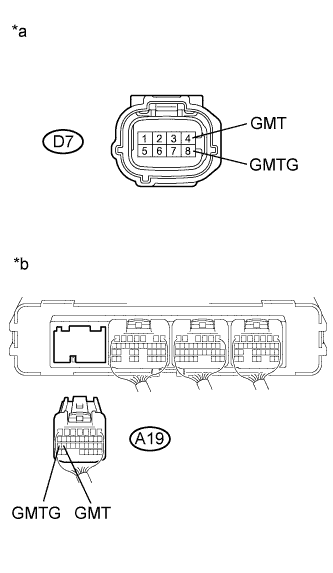 |
Measure the resistance according to the value(s) in the table below.
| Tester Connection | Switch Condition | Specified Condition |
| D7-4 (GMT) - A19-26 (GMT) | Power switch off | Below 1 Ω |
| D7-8 (GMTG) - A19-27 (GMTG) | Power switch off | Below 1 Ω |
| Tester Connection | Switch Condition | Specified Condition |
| D7-4 (GMT) or A19-26 (GMT) - Body ground and other terminals | Power switch off | 10 kΩ or higher |
| D7-8 (GMTG) or A19-27 (GMTG) - Body ground and other terminals | Power switch off | 10 kΩ or higher |
| *a | Front view of wire harness connector (to Generator Temperature Sensor) |
| *b | Rear view of wire harness connector (to Power Management Control ECU) |
Connect the power management control ECU connector.
Connect the generator temperature sensor connector.
|
| ||||
| OK | ||
| ||
| ||


