DTC    B1471/71    A/C Inverter High Voltage Power Resource System Malfunction

for Preparation Click here


DESCRIPTION

The A/C inverter assembly monitors the voltage of the battery. It stops compressor control and stores the DTC when the monitored voltage is outside the specified range.
The output DTC is memorized as previous trouble. Compressor control may not resume unless the power switch is turned off.

DTC No.
DTC Detection Condition
Trouble Area
B1471/71
  1. Open or short in A/C inverter high voltage power resource system.
  2. The boost inverter is broken or malfunctioning.
  1. Electric vehicle fuse
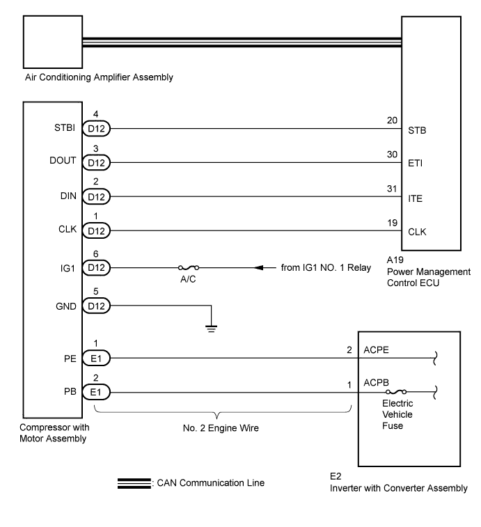
  2. No. 2 engine wire (harness or connector between compressor with motor assembly and inverter with converter assembly)
  3. Compressor with motor assembly
  4. Hybrid control system
  5. CAN communication system

WIRING DIAGRAM


E224018E07


INSPECTION PROCEDURE

CAUTION:
  1. Wear electrically insulated gloves and pull out the service plug grip before inspection as procedures may require disconnecting high-voltage connectors. Be sure to carry the removed service plug grip because other workers may install it by mistake.
  2. Do not touch the high-voltage connectors or terminals for 10 minutes after the service plug grip is removed.

NOTICE:
  1. After turning the power switch off, waiting time may be required before disconnecting the cable from the negative (-) battery terminal. Therefore, make sure to read the disconnecting the cable from the negative (-) battery terminal notices before proceeding with work (Click here).
  2. The hybrid control system and air conditioning system output DTCs separately. Inspect DTCs following the flow chart for the hybrid control system first if any DTCs from those systems are output simultaneously.

1.CHECK CAN COMMUNICATION SYSTEM
  1. Using the intelligent tester to check if the CAN communication system is functioning normally.

    Result:
    Result
    Proceed to
    CAN DTC is not output
    A
    CAN DTC is output
    B


B
GO TO CAN COMMUNICATION SYSTEM (Click here)
A


2.CHECK DIAGNOSTIC TROUBLE CODE (HYBRID CONTROL SYSTEM)
  1. Check if DTCs for the hybrid control system are output using the intelligent tester.

    OK:
    Hybrid control system DTCs are not output.


NG
GO TO HYBRID CONTROL SYSTEM (Click here)
OK


3.INSPECT ELECTRIC VEHICLE FUSE

CAUTION:
Be sure to wear insulated gloves.

  1. Turn the power switch off.

  1. Remove the service plug grip.

    CAUTION:
    Do not touch the high-voltage connectors or terminals for 10 minutes after the service plug grip is removed.

    NOTICE:
    After removing the service plug grip, turning the power switch on (READY) may cause a malfunction. Do not turn the power switch on (READY) with the service plug grip removed.

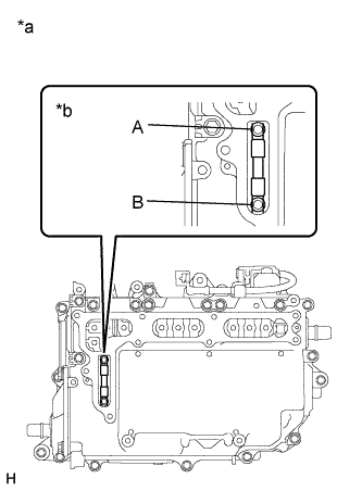
  1. Remove the inverter cover.

    NOTICE:
    Be sure to prevent foreign objects or water from entering the inverter with converter assembly.


    E222720E03
  1. Check that bolts A and B are tightened securely.

  1. Measure the resistance according to the value(s) in the table below.

    Standard Resistance:
    Tester Item
    (Tester Connection)
    Condition
    Specified Condition
    Electric vehicle fuse
    (A - B)
    Always
    Below 1 Ω

    Text in Illustration 
    *a
    Inverter with Converter Assembly
    *b
    Electric Vehicle Fuse


NG
REPLACE ELECTRIC VEHICLE FUSE
OK


4.INSPECT NO. 2 ENGINE WIRE

CAUTION:
Be sure to wear insulated gloves.

  1. Disconnect the No. 2 engine wire connector.

  1. Measure the resistance according to the value(s) in the table below.

    Standard Resistance:
    Tester Connection
    Condition
    Specified Condition
    E1-1 (PE) - E2-2 (ACPE)
    Always
    Below 1 Ω
    E1-2 (PB) - E2-1 (ACPB)
    Always
    Below 1 Ω
    E1-1 (PE) - Body ground
    Always
    10 kΩ or higher
    E1-2 (PB) - Body ground
    Always
    10 kΩ or higher


NG
REPLACE NO. 2 ENGINE WIRE (Click here)
OK

REPLACE COMPRESSOR WITH MOTOR ASSEMBLY (Click here)