DTC B1473/73 A/C Inverter Start-up Signal System Malfunction |
| DTC No. | DTC Detection Condition | Trouble Area |
| B1473/73 | Open or short in A/C inverter start-up signal system. |
|
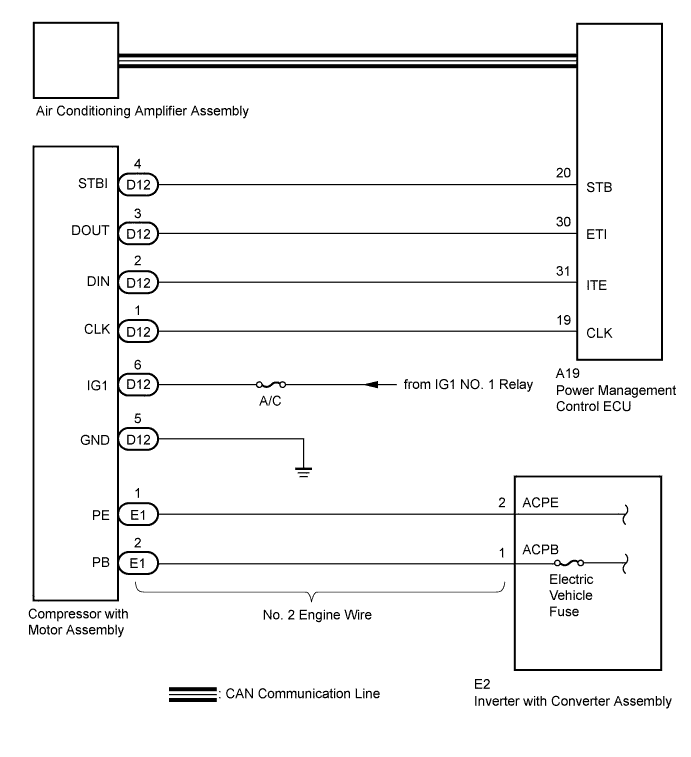
| 1.CHECK CAN COMMUNICATION SYSTEM |
Using the intelligent tester to check if the CAN communication system is functioning normally.
| Result | Proceed to |
| CAN DTC is not output | A |
| CAN DTC is output | B |
|
| ||||
| A | |
 |
| 2.CHECK DIAGNOSTIC TROUBLE CODE |
Check if DTCs for the air conditioning system and the hybrid control system are output using the intelligent tester.
| Result | Proceed to |
| Only DTC B1473 is output | A |
| DTCs B1473 and P3108 are output simultaneously (B1498 is not output) | |
| DTCs B1473 and B1498 are output simultaneously (P3108 is not output) | B |
| DTCs B1473, B1498 and P3108 are output simultaneously | |
| DTCs other than P3108 are output for hybrid control system | C |
|
| ||||
|
| ||||
| A | |
|
| 3.CHECK HARNESS AND CONNECTOR (POWER MANAGEMENT CONTROL ECU - COMPRESSOR WITH MOTOR) |
Disconnect the connector from the power management control ECU.
Disconnect the connector from the compressor with motor assembly.
Measure the resistance according to the value(s) in the table below.
| Tester Connection | Condition | Specified Condition |
| A19-20 (STB) - D12-4 (STBI) | Always | Below 1 Ω |
| A19-20 (STB) - Body ground | Always | 10 kΩ or higher |
|
| ||||
| OK | |
|
| 4.INSPECT COMPRESSOR WITH MOTOR ASSEMBLY |
Reconnect the connector to the compressor with motor assembly.
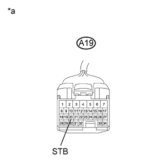 |
Measure the voltage according to the value(s) in the table below.
| Tester Connection | Condition | Specified Condition |
| A19-20 (STB) - Body ground | Power switch on (IG) | 11 to 14 V |
| A19-20 (STB) - Body ground | Power switch off | Below 1 V |
| *a | Front view of wire harness connector (to Power Management Control ECU) |
|
| ||||
| OK | ||
 | ||
| ||

