DTC B1475/75 A/C Inverter Cooling / Heating System Malfunction |
| DTC No. | DTC Detection Condition | Trouble Area |
| B1475/75 | Temperature of the inverter is outside the specified range (temperature is too high), or there is an open or short to ground in the temperature sensor circuit. |
|
| 1.CHECK CAN COMMUNICATION SYSTEM |
Using the intelligent tester to check if the CAN communication system is functioning normally.
| Result | Proceed to |
| CAN DTC is not output | A |
| CAN DTC is output | B |
|
| ||||
| A | |
 |
| 2.PERFORM ACTIVE TEST USING INTELLIGENT TESTER |
Connect the intelligent tester to the DLC3.
Turn the power switch on (IG).
Turn the intelligent tester on.
Enter the following menus: Powertrain / Engine and ECT / Active Test.
Check the operation by referring to the table below.
| Tester Display | Test Part | Control Range | Diagnostic Note |
| Control the Electric Cooling Fan | Electric cooling fan | OFF or ON | - |
|
| ||||
| OK | |
|
| 3.CHECK REFRIGERANT PRESSURE |
Install a manifold gauge set (Click here).
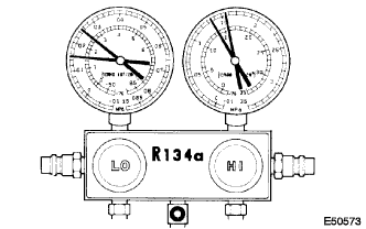 |
Read the manifold gauge pressure when the following conditions are established.
Prepare the vehicle according to the chart below.
| Item | Condition |
| Vehicle Doors | All fully open |
| Temperature Setting | MAX COLD |
| Blower Speed | HI |
| A/C switch | ON |
| R/F Switch | RECIRCULATION (30 to 35°C (86 to 95°F)) |
|
| ||||
| OK | |
|
| 4.READ OUTPUT DTC (DTC B1475/75) |
Clear the DTCs (Click here).
Prepare the vehicle according to the table below.
| Item | Condition |
| Engine speed | Engine idling |
| Blower speed | HI |
| A/C switch | ON |
| Temperature setting | MAX. COLD |
Check for DTCs (Click here).
| Result | Proceed to |
| DTC B1475/75 is not output (normal) | A |
| DTC B1475/75 is output | B |
|
| ||||
| A | ||
 | ||
| ||

