DTC P0A72-326 Generator Phase V Current |
DTC P0A72-328 Generator Phase V Current |
DTC P0A72-333 Generator Phase V Current |
DTC P0A72-515 Generator Phase V Current |
DTC P0A75-334 Generator Phase W Current |
DTC P0A75-336 Generator Phase W Current |
DTC P0A75-341 Generator Phase W Current |
DTC P0A75-516 Generator Phase W Current |
| DTC No. | INF Code | DTC Detection Condition | Trouble Area |
| P0A72 | 326 | Malfunction in generator inverter current sensor (phase V sub sensor) | Inverter with converter assembly |
| P0A72 | 328 | Malfunction in generator inverter current sensor (phase V main sensor) | |
| P0A72 | 333 | Malfunction in generator inverter current sensor (performance problem or open phase V) | |
| P0A72 | 515 | Malfunction in generator inverter current sensor (phase V main and sub sensors offset) | |
| P0A75 | 334 | Malfunction in generator inverter current sensor (phase W sub sensor) | |
| P0A75 | 336 | Malfunction in generator inverter current sensor (phase W main sensor) | |
| P0A75 | 341 | Malfunction in generator inverter current sensor (performance problem or open phase W) | |
| P0A75 | 516 | Malfunction in generator inverter current sensor (phase W main and sub sensors offset) |
| 1.CHECK DTC OUTPUT (HV) |
Connect the intelligent tester to the DLC3.
Turn the power switch on (IG).
Enter the following menus: Powertrain / Hybrid Control / DTC.
Check if DTCs are output.
| Result | Proceed to |
| P0A72 or P0A75 only is output. | A |
| P0A7A-203 is output. | B |
Turn the power switch off.
|
| ||||
| A | |
 |
| 2.CHECK CONNECTOR CONNECTION CONDITION (INVERTER WITH CONVERTER ASSEMBLY CONNECTOR) |
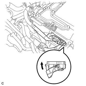 |
Check that the service plug grip is not installed.
Check the connection of the low voltage connector of the inverter with converter assembly.
|
| ||||
| OK | ||
 | ||
| ||

