DTC    P0A78-266    Drive Motor "A" Inverter Performance

DTC    P0A78-267    Drive Motor "A" Inverter Performance

for Preparation Click here


DESCRIPTION

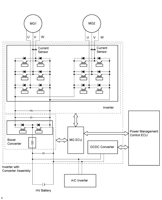
The inverter contains a three-phase bridge circuit, which consists of six power transistors (IGBTs) each for MG1 and MG2. The inverter converts high-voltage direct current from the HV battery into three-phase alternating current for MG1 and MG2; it also converts three-phase alternating current supplied by MG1 and MG2 into direct current for the HV battery. The MG ECU controls the actuation of the power transistors (IGBTs). The inverter transmits information necessary for control, such as amperage and voltage, to the MG ECU.

A216757E01

The MG ECU uses an inverter voltage sensor, which is built into the inverter, to detect boosted high voltage to allow control of the voltage boost.
The MG ECU monitors the inverter voltage sensor and detects the following malfunctions.

DTC No.
INF Code
DTC Detection Condition
Trouble Area
P0A78
266
Short to GND in the inverter voltage (VH) signal line
Inverter with converter assembly
P0A78
267
Open or short to +B in the inverter voltage (VH) signal line

INSPECTION PROCEDURE

1.REPLACE INVERTER WITH CONVERTER ASSEMBLY
  1. Replace the inverter with converter assembly (Click here).

HINT:
The signal line from the inverter voltage (VH) sensor is connected to the MG ECU inside the inverter with converter assembly. If P0A78-266 or P0A78-267 is output, replace the inverter with converter assembly.


NEXT

COMPLETED