FRONT POWER SEAT CONTROL SYSTEM (w/ Memory) > One or more Power Seat Motors do not Operate |
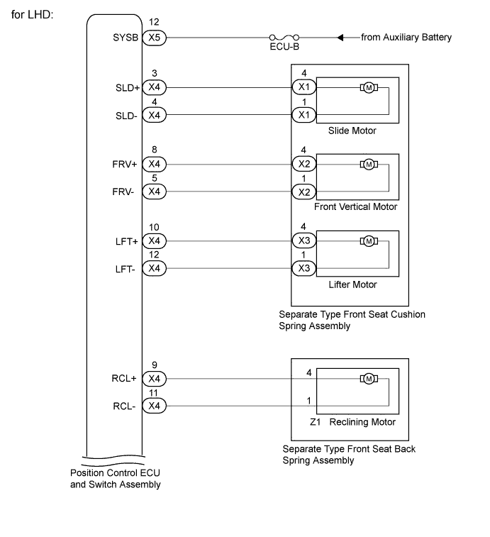
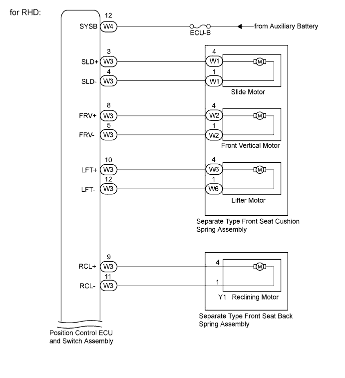
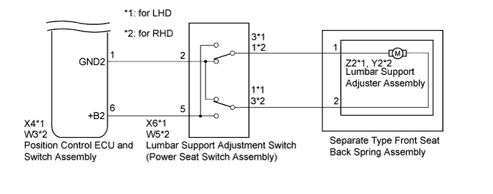
| 1.CHECK FRONT POWER SEAT OPERATION |
Check that each function of the power seat operates normally by using the power seat switch (Click here).
| Result | Proceed to |
| One or more power seat functions (except lumber support adjustment function) do not operate | A |
| All power seat functions do not operate | B |
| Front vertical and lifter functions do not operate | C |
| Only lumber support adjustment function does not operate | D |
|
| ||||
|
| ||||
|
| ||||
| A | |
 |
| 2.READ VALUE USING INTELLIGENT TESTER (POWER SEAT SWITCH) |
Connect the intelligent tester to the DLC3.
Turn the power switch on (IG).
Turn the intelligent tester on.
Enter the following menus: Body / Driver Seat / Data List.
Read the Data List according to the display on the intelligent tester.
| Tester Display | Measurement Item/Range | Normal Condition | Diagnostic Note |
| Reclining Rear | Reclining switch signal (Rearward) / ON or OFF | ON: Reclining switch (Rearward) on OFF: Reclining switch (Rearward) off | - |
| Reclining Front | Reclining switch signal (Forward) / ON or OFF | ON: Reclining switch (Forward) on OFF: Reclining switch (Forward) off | - |
| Front Vertical Down | Front vertical switch signal (Downward) / ON or OFF | ON: Front vertical switch (Downward) on OFF: Front vertical switch (Downward) off | - |
| Front Vertical Up | Front vertical switch signal (Upward) / ON or OFF | ON: Front vertical switch (Upward) on OFF: Front vertical switch (Upward) off | - |
| Lifter Switch Down | Lifter switch signal (Downward) / ON or OFF | ON: Lifter switch (Downward) on OFF: Lifter switch (Downward) off | - |
| Lifter Switch Up | Lifter switch signal (Upward) / ON or OFF | ON: Lifter switch (Upward) on OFF: Lifter switch (Upward) off | - |
| Slide Rear | Sliding switch signal (Rearward) / ON or OFF | ON: Sliding switch (Rearward) on OFF: Sliding switch (Rearward) off | - |
| Slide Front | Sliding switch signal (Forward) / ON or OFF | ON: Sliding switch (Forward) on OFF: Sliding switch (Forward) off | - |
|
| ||||
| A | |
|
| 3.PERFORM ACTIVE TEST USING INTELLIGENT TESTER (POWER SEAT MOTOR) |
Enter the following menus: Body / Driver Seat / Active Test.
Perform the Active Test according to the display on the intelligent tester.
| Tester Display | Test Part | Control Range | Diagnostic Note |
| Seat Reclining | Seat reclining operation | Front / OFF / Rear | - |
| Front Vertical Operation | Seat front vertical operation | Up / OFF / Down | - |
| Lifter Operation | Seat lifter operation | Up / OFF / Down | - |
| Seat Slide Operation | Seat sliding operation | Front / OFF / Rear | - |
| Result | Proceed to |
| The power seat functions operate normally. | A |
| Sliding, front vertical or lifter function does not operate normally. | B |
| Reclining function does not operate normally. | C |
|
| ||||
|
| ||||
| A | ||
 | ||
| ||
| 4.INSPECT SEPARATE TYPE FRONT SEAT CUSHION SPRING ASSEMBLY |
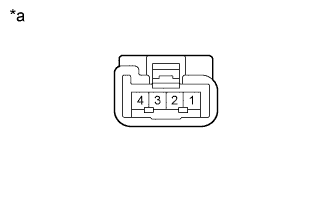 |
Disconnect the X1*1, X2*1, X3*1, W1*2, W2*2 or W6*2 connector from each motor.
Check the operation of the slide motor.
Check if the seat cushion moves smoothly when the auxiliary battery is connected to the slide motor connector terminals.
| Measurement Condition | Operational Direction |
| Auxiliary battery positive (+) → 4 Auxiliary battery negative (-) → 1 | Seat cushion spring moves forward |
| Auxiliary battery positive (+) → 1 Auxiliary battery negative (-) → 4 | Seat cushion spring moves backward |
| *a | Component without harness connected (Slide Motor (Separate Type Front Seat Cushion Spring Assembly)) |
|
Check the operation of the front vertical motor.
Check if the seat cushion moves smoothly when the auxiliary battery is connected to the front vertical motor connector terminals.
| Measurement Condition | Operational Direction |
| Auxiliary battery positive (+) → 4 Auxiliary battery negative (-) → 1 | Seat cushion spring moves upward |
| Auxiliary battery positive (+) → 1 Auxiliary battery negative (-) → 4 | Seat cushion spring moves downward |
| *a | Component without harness connected (Front Vertical Motor (Separate Type Front Seat Cushion Spring Assembly)) |
|
Check the operation of the lifter motor.
Check if the seat cushion moves smoothly when the auxiliary battery is connected to the lifter motor connector terminals.
| Measurement Condition | Operational Direction |
| Auxiliary battery positive (+) → 4 Auxiliary battery negative (-) → 1 | Seat cushion spring moves upward |
| Auxiliary battery positive (+) → 1 Auxiliary battery negative (-) → 4 | Seat cushion spring moves downward |
| *a | Component without harness connected (Lifter Motor (Separate Type Front Seat Cushion Spring Assembly)) |
| Result | Proceed to |
| NG | A |
| OK | B |
|
| ||||
| A | ||
| ||
| ||
| 5.INSPECT SEPARATE TYPE FRONT SEAT BACK SPRING ASSEMBLY |
|
Disconnect Z1*1 or Y1*2 reclining motor connector.
Check the operation of the reclining motor.
Check if the seat back moves smoothly when the auxiliary battery is connected to the reclining motor connector terminals.
| Measurement Condition | Operational Direction |
| Auxiliary battery positive (+) → 4 Auxiliary battery negative (-) → 1 | Seat back moves forward |
| Auxiliary battery positive (+) → 1 Auxiliary battery negative (-) → 4 | Seat back moves backward |
| *a | Component without harness connected (Reclining Motor (Separate Type Front Seat Back Spring Assembly)) |
|
| ||||
| OK | |
|
| 6.CHECK HARNESS AND CONNECTOR (POSITION CONTROL ECU AND SWITCH ASSEMBLY - POWER SEAT MOTOR) |
Disconnect the X4*1 or W3*2 position control ECU and switch assembly connector.
Measure the resistance according to the value(s) in the table below.
| Tester Connection | Condition | Specified Condition |
| X4-3 (SLD+) - X1-4 | Always | Below 1 Ω |
| X4-4 (SLD-) - X1-1 | Always | Below 1 Ω |
| X4-5 (FRV-) - X2-1 | Always | Below 1 Ω |
| X4-8 (FRV+) - X2-4 | Always | Below 1 Ω |
| X4-10 (LFT+) - X3-4 | Always | Below 1 Ω |
| X4-12 (LFT-) - X3-1 | Always | Below 1 Ω |
| X4-9 (RCL+) - Z1-4 | Always | Below 1 Ω |
| X4-11 (RCL-) - Z1-1 | Always | Below 1 Ω |
| X4-3 (SLD+) - Body ground | Always | 10 kΩ or higher |
| X4-4 (SLD-) - Body ground | Always | 10 kΩ or higher |
| X4-5 (FRV-) - Body ground | Always | 10 kΩ or higher |
| X4-8 (FRV+) - Body ground | Always | 10 kΩ or higher |
| X4-10 (LFT+) - Body ground | Always | 10 kΩ or higher |
| X4-12 (LFT-) - Body ground | Always | 10 kΩ or higher |
| X4-9 (RCL+) - Body ground | Always | 10 kΩ or higher |
| X4-11 (RCL-) - Body ground | Always | 10 kΩ or higher |
| Tester Connection | Condition | Specified Condition |
| W3-3 (SLD+) - W1-4 | Always | Below 1 Ω |
| W3-4 (SLD-) - W1-1 | Always | Below 1 Ω |
| W3-5 (FRV-) - W2-1 | Always | Below 1 Ω |
| W3-8 (FRV+) - W2-4 | Always | Below 1 Ω |
| W3-10 (LFT+) - W6-4 | Always | Below 1 Ω |
| W3-12 (LFT-) - W6-1 | Always | Below 1 Ω |
| W3-9 (RCL+) - Y1-4 | Always | Below 1 Ω |
| W3-11 (RCL-) - Y1-1 | Always | Below 1 Ω |
| W3-3 (SLD+) - Body ground | Always | 10 kΩ or higher |
| W3-4 (SLD-) - Body ground | Always | 10 kΩ or higher |
| W3-5 (FRV-) - Body ground | Always | 10 kΩ or higher |
| W3-8 (FRV+) - Body ground | Always | 10 kΩ or higher |
| W3-10 (LFT+) - Body ground | Always | 10 kΩ or higher |
| W3-12 (LFT-) - Body ground | Always | 10 kΩ or higher |
| W3-9 (RCL+) - Body ground | Always | 10 kΩ or higher |
| W3-11 (RCL-) - Body ground | Always | 10 kΩ or higher |
|
| ||||
| OK | ||
| ||
| ||
| 7.CHECK HARNESS AND CONNECTOR (POSITION CONTROL ECU AND SWITCH ASSEMBLY - BATTERY) |
Disconnect the X5*1 or W4*2 position control ECU and switch assembly connector.
Measure the voltage according to the value(s) in the table below.
| Tester Connection | Condition | Specified Condition |
| X5-12 (SYSB) - Body ground | Power switch off | 11 to 14 V |
| Tester Connection | Condition | Specified Condition |
| W4-12 (SYSB) - Body ground | Power switch off | 11 to 14 V |
|
| ||||
| OK | ||
| ||
| ||
| 8.INSPECT LUMBAR SUPPORT ADJUSTMENT SWITCH (POWER SEAT SWITCH ASSEMBLY) |
Remove the lumbar support adjustment switch (power seat switch assembly) (Click here).
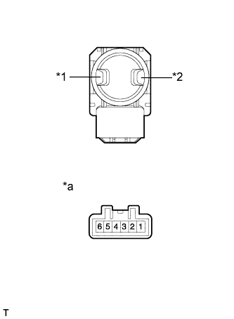 |
for LHD:
Measure the resistance according to the value(s) in the table below.
| Tester Connection | Switch Condition | Specified Condition |
| 3 - 5 | Hold | Below 1 Ω |
| 1 - 2 | ||
| 2 - 3 | Off | |
| 2 - 1 | ||
| 2 - 3 | Release | |
| 1 - 5 |
| *1 | Hold Switch |
| *2 | Release Switch |
| *a | Component without harness connected (Lumbar Support Adjustment Switch (Power Seat Switch Assembly)) |
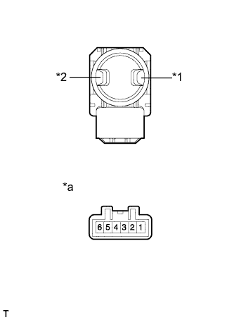 |
for RHD:
Measure the resistance according to the value(s) in the table below.
| Tester Connection | Switch Condition | Specified Condition |
| 1 - 5 | Hold | Below 1 Ω |
| 2 - 3 | ||
| 2 - 3 | Off | |
| 2 - 1 | ||
| 3 - 5 | Release | |
| 1 - 2 |
| *1 | Hold Switch |
| *2 | Release Switch |
| *a | Component without harness connected (Lumbar Support Adjustment Switch (Power Seat Switch Assembly)) |
|
| ||||
| OK | |
|
| 9.INSPECT LUMBAR SUPPORT ADJUSTER ASSEMBLY (SEPARATE TYPE FRONT SEAT BACK SPRING ASSEMBLY) |
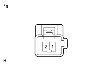 |
Disconnect Z2*1 or Y2*2 reclining motor connector.
Check the operation of the lumbar support adjuster assembly.
Check that the seat back moves smoothly when the auxiliary battery is connected to the lumbar support adjuster assembly connector terminals.
| Measurement Condition | Operational Direction |
| Auxiliary battery positive (+) → 1 Auxiliary battery negative (-) → 2 | Seat back moves forward |
| Auxiliary battery positive (+) → 2 Auxiliary battery negative (-) → 1 | Seat back moves backward |
| *a | Component without harness connected (Lumbar Support Adjuster Assembly (Separate Type Front Seat Back Spring Assembly)) |
|
| ||||
| OK | |
|
| 10.CHECK HARNESS AND CONNECTOR (LUMBAR SWITCH - POSITION CONTROL ECU AND LUMBAR MOTOR) |
Disconnect the X4*1 or W3*2 position control ECU and switch assembly connector.
Measure the resistance according to the value(s) in the table below.
| Tester Connection | Condition | Specified Condition |
| X4-6 (+B2) - X6-5 | Always | Below 1 Ω |
| X4-1 (GND2) - X6-2 | Always | Below 1 Ω |
| X6-3 - Z2-1 | Always | Below 1 Ω |
| X6-1 - Z2-2 | Always | Below 1 Ω |
| X6-5 - Body ground | Always | 10 kΩ or higher |
| X6-2 - Body ground | Always | 10 kΩ or higher |
| X6-3 - Body ground | Always | 10 kΩ or higher |
| X6-1 - Body ground | Always | 10 kΩ or higher |
| Tester Connection | Condition | Specified Condition |
| W3-6 (+B2) - W5-5 | Always | Below 1 Ω |
| W3-1 (GND2) - W5-2 | Always | Below 1 Ω |
| W5-3 - Y2-2 | Always | Below 1 Ω |
| W5-1 - Y2-1 | Always | Below 1 Ω |
| W5-5 - Body ground | Always | 10 kΩ or higher |
| W5-2 - Body ground | Always | 10 kΩ or higher |
| W5-3 - Body ground | Always | 10 kΩ or higher |
| W5-1 - Body ground | Always | 10 kΩ or higher |
|
| ||||
| OK | ||
| ||
| ||


