DTC    B2286    Runnable Signal Malfunction

for Preparation Click here


DESCRIPTION

This DTC is stored when a malfunction is detected in the READY signal circuit inside the power management control ECU.

HINT:
  1. When the power management control ECU is replaced with a new one and the cable from the negative (-) auxiliary battery terminal is connected, the power source mode becomes the on (IG) mode. When the auxiliary battery is removed and reinstalled, the power source mode that was selected when the auxiliary battery was removed is restored.
  2. When the auxiliary battery cable is disconnected and reconnected, the power source returns to the mode it was in before the auxiliary battery cable was disconnected.


DTC No.
DTC Detection Condition
Trouble Area
B2286
READY signal error inside the power management control ECU.
  1. AM2 fuse
  2. Power management control ECU
  3. Wire harness or connector

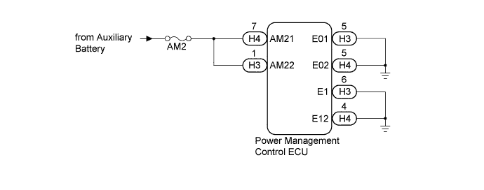
WIRING DIAGRAM


B230178E10


INSPECTION PROCEDURE

NOTICE:
  1. When using the intelligent tester with the power switch off, perform either of the following: 1) Turn a courtesy light switch on and off at intervals of 1.5 seconds or less until communication between the intelligent tester and vehicle begins, or 2) connect the intelligent tester to the vehicle, select the vehicle type under manual mode, and then enter the following menus:
    for Power Source Control: Body / Power Source Control / DTC.
    for Entry&Start: Body / Entry&Start / DTC.
  2. The push-button start system uses multiplex communication. First perform the inspections in "How to Proceed with Troubleshooting" to confirm that there are no communication malfunctions before proceeding with troubleshooting (Click here).
  3. Inspect the fuses for circuits related to this system before performing the following inspection procedure.
  4. After performing repairs, perform the operation that fulfills the DTC output confirmation operation, and then confirm that no DTCs are output again.

HINT:
Check the connector connection to the terminal to make sure that there is no abnormality such as a loose connection, deformation, etc.

1.CHECK HARNESS AND CONNECTOR (AUXILIARY BATTERY - POWER MANAGEMENT CONTROL ECU)
  1. Disconnect the H3 and H4 connectors from the power management control ECU.

  1. Measure the voltage according to the value(s) in the table below.

    Standard Voltage:
    Tester Connection
    Condition
    Specified Condition
    H3-1 (AM22) - Body ground
    Always
    9.5 to 16 V
    H4-7 (AM21) - Body ground
    Always
    9.5 to 16 V


NG
REPAIR OR REPLACE HARNESS OR CONNECTOR
OK


2.CHECK HARNESS AND CONNECTOR (POWER MANAGEMENT CONTROL ECU - BODY GROUND)
  1. Measure the resistance according to the value(s) in the table below.

    Standard Resistance:
    Tester Connection
    Condition
    Specified Condition
    H3-5 (E01) - Body ground
    Always
    Below 1 Ω
    H3-6 (E1) - Body ground
    Always
    Below 1 Ω
    H4-4 (E12) - Body ground
    Always
    Below 1 Ω
    H4-5 (E02) - Body ground
    Always
    Below 1 Ω


NG
REPAIR OR REPLACE HARNESS OR CONNECTOR
OK


3.CHECK FOR DTC
  1. Clear the DTCs (Click here).

  1. Turn the power switch on (READY).

  1. After 25 seconds have elapsed, check if the DTC has been set again.

    OK:
    DTC B2286 is not output


NG
REPLACE POWER MANAGEMENT CONTROL ECU (Click here)
OK

USE SIMULATION METHOD TO CHECK (Click here)