AIRBAG SYSTEM > SRS Warning Light Remains ON |
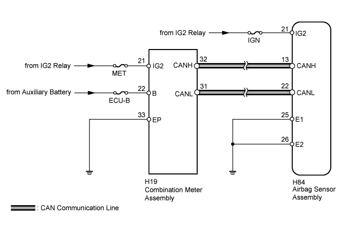
| 1.CHECK SRS WARNING LIGHT OPERATION |
Check the SRS warning light operation approximately 6 seconds after the power switch is turned on (IG).
| SRS Warning Light Illumination | Proceed to |
| Remains on | A |
| Goes off and then comes on again | B |
|
| ||||
| A | |
 |
| 2.CHECK AUXILIARY BATTERY VOLTAGE |
Measure the voltage of the auxiliary battery.
|
| ||||
| OK | |
|
| 3.CHECK CONNECTOR |
Turn the power switch off.
Disconnect the cable from the negative (-) auxiliary battery terminal.
Check that the connector is properly connected to the airbag sensor assembly.
Disconnect the connector from the airbag sensor assembly.
Check that the terminal of the connector is not damaged.
|
| ||||
| OK | |
|
| 4.CHECK WIRE HARNESS (AIRBAG SENSOR ASSEMBLY - BODY GROUND) |
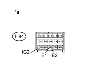 |
Connect the cable to the negative (-) auxiliary battery terminal.
Turn the power switch on (IG).
Operate all components of the electrical system (defogger, wipers, headlights, heater blower, etc.).
Measure the voltage according to the value(s) in the table below.
| Tester Connection | Switch Condition | Specified Condition |
| H84-21 (IG2) - Body ground | Power switch on (IG) | 8 to 16 V |
Turn the power switch off.
Measure the resistance according to the value(s) in the table below.
| Tester Connection | Condition | Specified Condition |
| H84-25 (E1) - Body ground | Always | Below 1 Ω |
| H84-26 (E2) - Body ground | Always | Below 1 Ω |
| *a | Front view of wire harness connector (to Airbag Sensor Assembly) |
|
| ||||
| OK | |
|
| 5.CHECK SRS WARNING LIGHT |
Turn the power switch on (IG).
Check the SRS warning light condition.
|
| ||||
| OK | ||
 | ||
| ||
| 6.CHECK CAN COMMUNICATION SYSTEM |
Use the intelligent tester to check if the CAN communication system is functioning normally.
| Result | Proceed to |
| DTC is not output | A |
| DTC is output | B |
|
| ||||
| A | |
|
| 7.CHECK AUXILIARY BATTERY VOLTAGE |
Measure the voltage of the auxiliary battery.
|
| ||||
| OK | |
|
| 8.CHECK CONNECTOR |
Turn the power switch off.
Disconnect the cable from the negative (-) auxiliary battery terminal.
Check that the connector is properly connected to the airbag sensor assembly.
Disconnect the connector from the airbag sensor assembly.
Check that the terminal of the connector is not damaged.
|
| ||||
| OK | |
|
| 9.CHECK WIRE HARNESS (AIRBAG SENSOR ASSEMBLY - BODY GROUND) |
|
Connect the cable to the negative (-) auxiliary battery terminal.
Turn the power switch on (IG).
Operate all components of the electrical system (defogger, wipers, headlights, heater blower, etc.).
Measure the voltage according to the value(s) in the table below.
| Tester Connection | Switch Condition | Specified Condition |
| H84-21 (IG2) - Body ground | Power switch on (IG) | 8 to 16 V |
Turn the power switch off.
Measure the resistance according to the value(s) in the table below.
| Tester Connection | Condition | Specified Condition |
| H84-25 (E1) - Body ground | Always | Below 1 Ω |
| H84-26 (E2) - Body ground | Always | Below 1 Ω |
| *a | Front view of wire harness connector (to Airbag Sensor Assembly) |
|
| ||||
| OK | |
|
| 10.CHECK CONNECTOR |
Disconnect the cable from the negative (-) auxiliary battery terminal.
Check that the connector is properly connected to the combination meter assembly.
Disconnect the connector from the combination meter assembly.
Check that the terminal of the connector is not damaged.
|
| ||||
| OK | |
|
| 11.CHECK WIRE HARNESS (COMBINATION METER ASSEMBLY - BODY GROUND) |
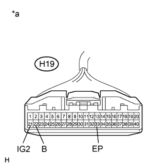 |
Connect the cable to the negative (-) auxiliary battery terminal.
Turn the power switch on (IG).
Measure the voltage according to the value(s) in the table below.
| Tester Connection | Condition | Specified Condition |
| H19-21 (IG2) - Body ground | Power switch on (IG) | 11 to 14 V |
| H19-22 (B) - Body ground | Always | 11 to 14 V |
Turn the power switch off.
Measure the resistance according to the value(s) in the table below.
| Tester Connection | Condition | Specified Condition |
| H19-33 (EP) - Body ground | Always | Below 1 Ω |
| *a | Front view of wire harness connector (to Combination Meter Assembly) |
|
| ||||
| OK | |
|
| 12.CHECK SRS WARNING LIGHT |
Disconnect the cable from the negative (-) auxiliary battery terminal.
Connect the connector to the combination meter assembly.
Connect the cable to the negative (-) auxiliary battery terminal.
Turn the power switch on (IG).
Check the SRS warning light condition.
|
| ||||
| OK | ||
| ||
| ||


